4.2 ESSENTIAL COMPONENTS OF AN AQUAPONIC UNIT
All aquaponic systems share several common and essential components. These include: a fish tank, a mechanical filter, a biofilter, and hydroponic containers. All systems use energy to circulate water through pipes and plumbing while aerating the water. As introduced above, there are three main designs of the plant growing areas including: grow beds, grow pipes and grow canals. This section discusses the mandatory components, including the fish tanks, mechanical filter, biofilter, plumbing and pumps. The following sections are dedicated to the separate hydroponic techniques, and a comparison is made to determine the most appropriate combination of techniques for different circumstances.
4.2.1 Fish tank
Fish tanks are a crucial component in every unit. As such, fish tanks can account for up to 20 percent of the entire cost of an aquaponic unit. Fish require certain conditions in order to survive and thrive, and therefore the fish tank should be chosen wisely. There are several important aspects to consider, including the shape, material and colour.
Tank shape
Although any shape of fish tank will work, round tanks with flat bottoms are recommended. The round shape allows water to circulate uniformly and transports solid wastes towards the centre of the tank by centripetal force. Square tanks with flat bottoms are perfectly acceptable, but require more active solid-waste removal. Tank shape greatly affects water circulation, and it is quite risky to have a tank with poor circulation. Artistically shaped tanks with non-geometric shapes with many curves and bends can create dead spots in the water with no circulation. These areas can gather wastes and create anoxic, dangerous conditions for the fish. If an odd-shaped tank is to be used, it may be necessary to add water pumps or air pumps to ensure proper circulation and remove the solids. It is important to choose a tank to fit the characteristics of the aquatic species reared because many species of bottom dwelling fish show better growth and less stress with adequate horizontal space.
Material
Either strong inert plastic or fibreglass is recommended because of their durability and long life span. Metal is not possible because of rust. Plastic and fibreglass are convenient to install (also for plumbing) and are fairly light and manoeuvrable. Animal-watering troughs are commonly used, as they tend to be cheap. If using plastic containers, make sure that they are UV-resistant because direct sunlight can destroy plastic. In general, low-density polyethylene (LDPE) tanks are preferable because of their high resistance and food-grade characteristics. Indeed, LDPE is the most commonly used material for water storage tanks for civil uses. Another option is an in-ground pond. Natural ponds are very difficult to manage for aquaponics because the natural biological processes, already occurring within the substrate and mud at the bottom, can be hard to manipulate and the nutrients are often already used by aquatic plants. Cement or plastic-lined ponds are much more acceptable, and can be an inexpensive option. In-ground ponds can make plumbing operations difficult, and the plumbing design. should be carefully considered before embarking on this option. One of the simplest fish tanks is a hole dug in the ground, lined with bricks or cinderblocks, and then lined with a waterproof liner such as polyethylene plastic. Other options include second- hand containers, such as bathtubs, barrels or intermediate bulk containers (IBCs). It is very important to make sure the container has not been used previously to store toxic material. Contaminants, such as solvent-borne chemicals, will have penetrated into the porous plastic itself and are impossible to remove with washing. Thus, choose used containers carefully, and know the seller if possible.
Colour
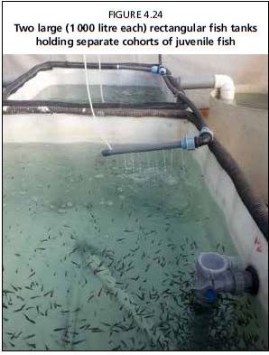
White or other light colours are strongly advised as they allow easier viewing of the fish in order to easily check behaviour and the amount of waste settled at the bottom of the tank (Figures 4.22- 4.24). White tanks will also reflect sunlight and keep the water cool. Alternatively, the outside of darker coloured tanks can be painted white. In very hot or cold areas, it may be necessary to further thermally insulate the tanks.
Covers and shading
All fish tanks should be covered. The shade covers prevent algal growth. In addition, the covers prevent fish from jumping out (often occurs with newly added fish or if water quality is sub-optimal), prevent leaves and debris from entering, and prevent predators such as cats and birds from attacking the fish. Often, agricultural shading nets that block 80-90 percent of sunlight are used. The shade cloth can be attached to a simple wooden frame to provide weight and make the cover easy to remove.
Failsafe and redundancy
Do not let the fish tank lose its water; fish will die if the fish tank accidentally drains. Although some accidents are unavoidable (e.g. a tree falling on the tank), most catastrophic fish kills are the result of human error. Ensure that
FIGURE 4.22
A 1000 litre fish tank made from a white polyethylene drum
FIGURE 4.23
Young fish in a cylindrical aquaponic tank. Return line (top) and bottom drain clearly visible
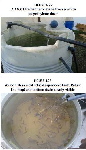
FIGURE 4.24
Two large (1 000 litre each) rectangular fish tanks holding separate cohorts of juvenile fish
there is no way for the tank to drain without a deliberate choice by the operator. If the water pump is located in the fish tank, be sure to lift the pump off the bottom so that the tank can never be pumped dry. Use a standpipe inside the tank to guarantee a minimum water level. This is discussed further in Section 4.2.6.
4.2.2 Filtration mechanical and biological
Mechanical filtration
For RASS, mechanical filtration is arguably the most important aspect of the design. Mechanical filtration is the separation and removal of solid and suspended fish waste from fish tanks. It is essential to remove these wastes for the health of the system, because harmful gases are released by anaerobic bacteria if solid waste is left to decompose inside the fish tanks. Moreover, the wastes can clog systems and disrupt water flow, causing anoxic conditions to the plant roots. Small-scale aquaponics typically has lower stocking densities than the intensive RAS methods for which these mechanical filters were originally designed, but some level of mechanical filtration is essential for healthy aquaponic tanks, regardless of the type of hydroponic method used.
There are several types of mechanical filters. The simplest method is a screen or filter located between the fish tank and the grow bed. This screen catches solid wastes, and needs to be rinsed often. Similarly, water leaving the fish tank can pass through a small container of particulate material, separate from the media bed; this container is easier to rinse periodically. These methods are valid for some small-scale aquaponic units, but are insufficient in larger systems with more fish where the amount of solid waste is relevant. There are many types of mechanical filters, including sedimentation tanks, radial-flow clarifiers, sand or bead filters and baffle filters; each of them can be used according to the amount of solid wastes that needs to be removed. However, as this publication focuses on small-scale aquaponics, clarifiers, or mechanical separators, are the most appropriate filters. Clarifiers, in general, can remove up to 60 percent of the total removable solids. For further information on different methods of mechanical filtration, please refer to the further reading section at the end of this publication.
Mechanical separators (clarifiers)
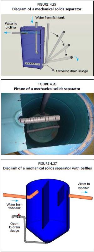
A clarifier is a dedicated vessel that uses the properties of water to separate particles. Generally, water that is moving slower is unable to carry as many particles as water that is flowing faster. Therefore, the clarifier is constructed in such a way as to speed up and slow down the water so that the particles concentrate on the bottom and can be removed. In a swirl clarifier, the water from the fish tank enters near the lower- middle of the clarifier through a pipe. This pipe is positioned tangentially to the container thereby forcing the water to swirl in a circular motion inside the container. The centripetal force created by the circular motion of the water forces the solid waste in the water to the centre and bottom of the container, because the water in the centre of the vortex is slower than that on the outside. Once this waste is collected on the bottom, a pipe attached to the bottom of the container can be periodically opened, allowing the solid waste to flush out of the container. The clarified water exits the clarifier at the top, through a large slotted outlet pipe covered with a secondary mesh filter, and flows into the biofilter or into the media beds. Figures 4.25-4.27 show examples of simple mechanical separators for small to large units. The solid wastes trapped and removed contain nutrients and are very useful for the systems or for garden plants in general; mineralization of solid waste is discussed in the following section. A general guideline for small-scale units is to size the mechanical separator container to be about one-sixth the volume of the fish tank, but this depends on stocking density and the exact design. Appendix 8 contains detailed, step-by- step instruction on the construction of each part of these systems.
Adequate preliminary mechanical filtration is especially important for NFT and DWC units used to trap and remove solid waste. Without this preliminary process, solid and suspended waste will build up in the grow pipes and canals and will clog the root surfaces. Solid waste accumulation causes blockages in pumps and plumbing components. Finally, unfiltered wastes will also create hazardous anaerobic spots in the system. These anaerobic spots can harbour bacteria that produce hydrogen sulphide, a very toxic and lethal gas for fish, produced from fermentation of solid wastes, which can often be detected as a rotten egg smell.
Biofiltration
Biofiltration is the conversion of ammonia and nitrite into nitrate by living bacteria. Most fish waste is not filterable using a mechanical filter because the waste is dissolved directly in the water, and the size of these particles is too small to be mechanically removed. Therefore, in order to process this microscopic waste an aquaponic system uses microscopic bacteria. Biofiltration is essential in aquaponics because ammonia and nitrite are toxic even at low concentrations, while plants need the nitrates to grow. In an aquaponic unit, the biofilter is a deliberately installed component to house a majority of the living bacteria. Furthermore, the dynamic
FIGURE 4.25 Diagram of a mechanical solids separator
FIGURE 4.26 Picture of a mechanical solids separator
FIGURE 4.27 Diagram of a mechanical solids separator with baffles
movement of water within a biofilter will break down very fine solids not captured by the clarifier, which further prevents waste build up on plant roots in NFT and DWC. However, some large aquaponic facilities following the design of the system developed at the University of the Virgin Islands do not use a separate biofilter as they mostly rely on the units' wet surfaces, on plant roots and direct plant uptake to process ammonia. Separate biofiltration is unnecessary in the media bed technique because the grow beds themselves are perfect biofilters.
Water to biofilter
FIGURE 4.28 Diagram of a biofilter for small-scale nutrient film technique and deep water culture units
FIGURE 4.29
Water from clarifier
Detail of plastic biofilter medium with large specific surface area
FIGURE 4.30
Details of biofilter showing the (a) additional mechanical filtration and (b) the biofilter medium
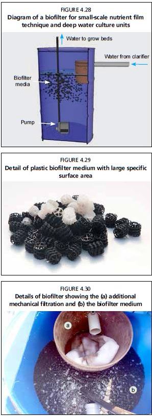
The biofilter is designed to have a large surface area supplied with oxygenated water. The biofilter is installed between the mechanical filter and the hydroponic containers. The minimum volume of this biofilter container. should be one-sixth that of the fish tank. Figure 4.28 shows an example of a biofilter for small-scale units.
One commonly used biofilter medium is BioballsR a proprietary product available from aquaculture supply stores, although similar generic brands exist (Figure 4.29). These are designed to be an ideal biofilter material, because they are small, specially shaped plastic items that have a very large surface area for their volume (500-700 m2/m3). Other media can be used, including volcanic gravel, plastic bottle caps, nylon shower poufs, netting, polyvinyl chloride (PVC) shavings and nylon scrub pads. Any biofilter needs to have a high ratio of surface area to volume, be inert and be easy to rinse. Bioballs have almost double the surface area to volume ratio of volcanic gravel, and both have a higher ratio than plastic bottle caps. When using suboptimal biofilter material, it is important to fill the biofilter as much as possible, but even so the surface provided by the media may be not sufficient to ensure adequate biofiltration. It is always better to oversize the biofilter during the initial construction, but secondary biofilters can be added later if necessary. Biofilters occasionally need stirring or agitating to prevent clogging, and occasionally need rinsed if the solid waste has clogged them, creating anoxic zones. See Chapter 8 and Appendix 4 for further information on biofiltration size requirements for small-scale units.
Another required component for the biofilter is aeration. Nitrifying bacteria need adequate access to oxygen in order to oxidize the ammonia. One easy solution is to use an air pump, placing the air stones at the bottom of the container. This ensures that the bacteria have constantly high and stable DO concentrations. Air pumps also help break down any solid or suspended waste not captured by the mechanical separator by agitating and constantly moving the floating Bioballs®. To further trap solids within the biofilter, it is also possible to insert a small cylindrical plastic bucket full of nylon netting (such as Perlon®), sponges or a net bag full of volcanic gravel at the inlet of the biofilter (Figure 4.30). The waste is trapped by this secondary mechanical filter, allowing the remaining water to flow down through small holes drilled at the bottom of the bucket into the biofilter container. The trapped waste is also subject to mineralization and bacterial degradation.
Mineralization
Mineralization, in terms of aquaponics, refers to the way that solid wastes are processed and metabolized by bacteria into nutrients for plants. Solid wastes that are trapped by the mechanical filter contain nutrients; although processing these wastes is different from biofiltration and requires separate consideration. Retaining the solids within the overall system will add more nutrients back to the plants. Any waste that remains on the mechanical filters, within the biofilters or in the grow beds is subjected to some mineralization. Leaving the waste in place for longer allows more mineralization; longer residence time of the waste in the filters will lead to more mineralization and more nutrients being retained in the system. However, this same solid waste, if not properly managed and mineralized, will block water flow, consume oxygen and lead to anoxic conditions, which in turn lead to dangerous hydrogen sulphide gas production and denitrification. Some large systems therefore deliberately leave the solid waste within the filters, ensuring adequate water flow and oxygenation, so that a maximum of the nutrients is released. However, this method is impractical for small-scale NFT and DWC systems. If it is decided to deliberately mineralize these solids, there are simple ways to facilitate the bacterial breakdown in a separate container, simply storing these wastes in this separate container with adequate oxygenation using air stones. After an indefinite amount of time, the solid waste will have been consumed, metabolized and transformed by heterotrophic bacteria At this point, the water can be decanted and re-added to the aquaponic system, and the remaining waste, which has decreased in volume, can be added to the soil.
Alternatively, these solid wastes can be separated, removed and added to any in-ground agriculture, garden or compost bin as a valuable fertilizer. However, losing these nutrients can cause deficiencies in the plants which may then require supplementation of nutrients (see Chapter 6).
Using a media bed for a combination of mechanical and biological filtration
It is also possible to use a media-filled bed for mechanical and biofiltration in NFT and DWC units (Figures 4.31 and 4.32). This can be important where it is not possible to obtain the materials needed for a swirl separator and/or separate biofilter. Although more fully discussed in Chapter 8, here it is sufficient to say that for every 200 g of fish feed per day the biofilter needs to be 300 litres in volume. This small gravel would provide adequate biofiltration for about 20 kg of fish. Although this media bed would provide adequate biofiltration for an NFT or DWC unit as well as capturing and retaining solid wastes, an additional solids capture device placed into the bed is sometimes recommended in order to prevent the media bed
FIGURE 4.31
Small-scale media bed unit using a screen for additional mechanical filtration
FIGURE 4.32
A media bed unit used for filtration in a deep water culture system
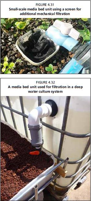
FIGURE 4.33
Diagram of a mechanical solids separator (right) connected to
FIGURE 4.34
Top view of mechanical solids separator (right) connected to the biofilter (left)
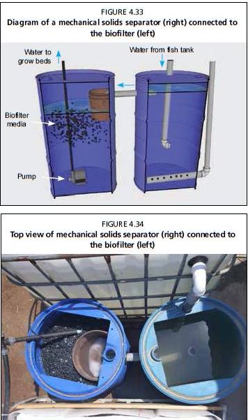
from clogging with fish solids. The bed will need rinsing periodically to remove solid wastes.
In summary, some level of filtration is essential to all aquaponics, although fish stocking density and system design determines how much filtration is necessary. Mechanical filters separate solid wastes to prevent toxic build up, and biofiltration converts dissolved nitrogenous wastes into nitrate (Figures 4.33 and 4.34). The media. beds themselves act as both mechanical filters and biofilters when using that technique, but additional mechanical filtration is sometimes necessary for higher fish densities (15 kg/m3). Without the media beds, such as in NFT and DWC units, standalone filtration is necessary. Mineralization of solid wastes returns more nutrients to the system. Mineralization occurs in media beds, but within NFT and DWC systems separate apparatus are needed.
4.2.3 Hydroponic components - media beds, NFT, DWC
The hydroponic component is the term to describe the plant-growing sections in the unit. There are several designs, three of which are discussed in detail in this publication, but each warrants a separate section. These three designs are: media bed units, sometimes called particulate beds, where plants grow within a substrate (Figures 4.35 and 4.36); nutrient film technique (NFT) units, where plants grow with their roots in wide pipes supplied with a trickle of culture water (Figure 4.37 and 4.38); and deep water culture (DWC)
FIGURE 4.35
Vegetables growing in a media bed unit
FIGURE 4.36
Different vegetable plants growing in the same media bed
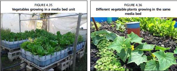
FIGURE 4.37
Detail of lettuce plants growing in circular pipes of a nutrient film technique unit
FIGURE 4.38
Lettuce growing in square pipes of a nutrient film technique unit
FIGURE 4.39
Swiss chard (Beta sp.) suspended on a polystyrene raft in a deep water culture canal
FIGURE 4.40
Lettuce growing densely in small deep water culture unit
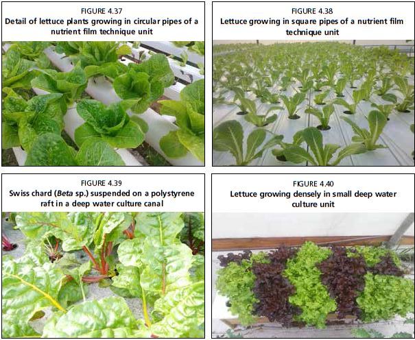
units, also called raft aquaponics or floating bed systems, where plants are suspended above a tank of water using a floating raft (Figure 4.39 and 4.40). Each method has advantages and disadvantages, all with different component styles to suit the needs of each method. See Sections 4.3-4.6 for details of each.
4.2.4 Water movement
Water movement is fundamental for keeping all organisms alive in aquaponics. The flowing water moves from the fish tanks, through the mechanical separator and the biofilter and finally to the plants in their media beds, pipes or canals, removing the dissolved nutrients. If water movement stops, the most immediate effect will be a reduction in DO and accumulation of wastes in the fish tank; without the mechanical filter and biofilter fish can suffer and die within a few hours. Without water flow, the water in media beds or DWC units will stagnate and become anoxic, and NFT systems will dry out.
A commonly cited guideline for densely-stocked aquaponic systems is to cycle the water two times per hour. For example, if an aquaponic unit has a total water volume of 1000 litres, the water flow rate should be 2 000 litres/h, so that every hour the water is cycled two times. However, at low stocking densities this turnover rate is unnecessary, and the water only needs to be cycled one time per hour. There are three commonly used methods of moving water through a system: submersible impeller pumps, airlifts and human power.
Submersible impeller water pump
Most commonly, an impeller-type submersible water pump is used as the heart of ant aquaponics unit, and this type of pump is recommended (Figure 4.41). External pumps
FIGURE 4.41
Submersible water pump, commercially available in many brands, used in small-scale aquaponic units
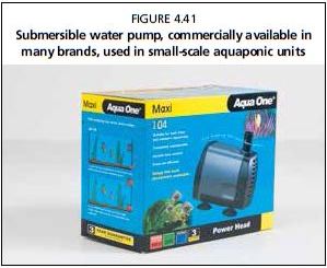
could be used, but they require further plumbing and are more appropriate for larger designs. High-quality water pumps should preferably be used in order to guarantee a long life span and energy efficiency. Top-quality pumps will maintain their pumping capacity and efficiency for least 1-2 years, with an overall life span of 3-5 years, whereas inferior products will lose their pumping power in a shorter time leading to significantly reduced water flows. Regarding flow rate, the small-scale units described in this publication need a flow rate of 2 000 litres/h at a head height of 1.5 meters; a submersible pump of this capacity would consume 25-50 W/h. A helpful approximation to calculate energy efficiency for submersible pumps is that a pump can move 40 litres of water per hour for every watt per hour consumed, although some models claim twice this efficiency.
Power Head
When designing the plumbing for the pump, it is important to realize that pumping power is reduced at every pipe fitting; up to 5 percent of the total flow rate can be lost at each pipe connection when water is forced through. Thus, use the minimal number of connections between the pump and the fish tanks. It is also important to note that the smaller the diameter of the pipes, the larger the water flow loss. A 30 mm pipe has twice the flow of a 20 mm pipe even if served from pumps with same capacity. In addition, a larger pipe does not require any maintenance to remove the buildup of solids accumulating inside. In practical terms, this results in significant savings on electricity and operating costs. When installing an aquaponic unit, be sure to place the submersible pump in an accessible location because periodic cleaning is necessary. Indeed, the internal filter will need cleaning every 2-3 weeks. Submersible water pumps will break if they are run without water, never run a pump dry.
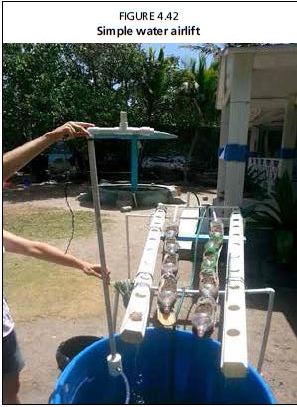
FIGURE 4.42 Simple water airlift
Airlift
Airlifts are another technique of lifting water (Figure 4.42). They use an air pump rather a water pump. Air is forced to the bottom of a pipe within the fish tank, bubbles form and burst, and during their rise to the surface the bubbles transport water with them. One benefit is that airlifts can be more electrically efficient, but only at small head heights (30-40 cm). Air lifts gain power in deeper tanks, and are best at a depth greater than one metre. An added value is that airlifts do not clog the way that submersible impeller-type pumps do. In addition, water is also oxygenated through the vertical movement operated by the air bubbles. However, the volume of air pumped should be adequate to move the water along the pipe.. Air pumps generally have a longer life than submersible water pumps. The main benefit comes from an economy of scale a single air pump can be purchased for both aeration and water circulation, which reduces the capital investment in a second pump.
Human power
Some aquaponic systems have been designed to use human power to move water (Figure 4.43). Water can be lifted in buckets or by using pulleys, modified bicycles or other means. A header tank can be filled manually and allowed to slowly drain throughout the course of the day. These methods are only applicable for small systems, and should only be considered where electricity is unavailable or unreliable. Often these systems will have low DO and insufficient mixing of nutrients, although they can be used successfully in conjunction with some modified techniques discussed in Chapter 9.
4.2.5 Aeration
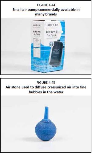
Air pumps inject air into the water through. air pipes and air stones that lie inside the water tanks, thereby increasing the DO levels in the water (Figure 4.44). Additional DO is a vital component of NFT and DWC units. Air stones are located at the end of the air line, and serve to diffuse the air into smaller bubbles (Figure 4.45). Small bubbles have more surface area, and therefore release oxygen into water better than large bubbles; this makes the aeration system more efficient and contributes to saving on costs. It is recommended that quality air stones be used in order to obtain the smallest air bubbles. Biofouling will occur, and air stones should be cleaned regularly first with a chlorine solution to kill bacterial deposits and then, if necessary, with a very mild acid to remove mineralization, or replaced, when the flow of bubbles is inconsistent. Quality air pumps are an irreplaceable component of aquaponic systems, and many systems have been saved from catastrophic collapse because of an abundance of DO. If possible, it is preferable to use a combination AC/DC air pump in case of electricity shortages, because when disconnected from AC power during an outage, the charged DC batteries can continue working.
Sizing aeration systems
For small-scale units, with about 1 000 litre fish tanks, it is recommended that at least two air lines, also called injectors, with air stones should be placed in the fish tank, and one injector in the biofilter container. To understand the volume of air entering the system, it is worth measuring
FIGURE 4.43
Backyard aquaponic system without the use of a water pump
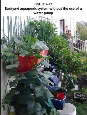
FIGURE 4.44
Small air pump commercially available in many brands
FIGURE 4.45
Air stone used to diffuse pressurized air into fine bubbles in the water
the flow rate. To do this, simply invert a volumetric measuring device (a 2 litre bottle, measuring cup, graduated beaker) in the fish tank. With the help of an assistant, begin a stopwatch at the same time as the bubbling air stone is inserted into the measuring device. Stop the stopwatch when the container is full of air. Then, determine the flow rate in litres per minute using a ratio. The target for systems described here is 4-8 litres/ min for all of the air stones combined. It is always better to have extra DO rather than not enough.
Try to place air stones so that they do not re-suspend settling solids, thus preventing their removal through the centre drain.
Venturi siphons
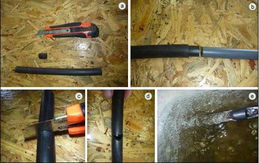
Low-tech and simple to construct, Venturi siphons are another technique to increase the DO levels in aquaponics. This technique is especially valuable in DWC canals. Simply speaking, Venturi siphons use a hydrodynamic principle that pulls in air from the outside (aspiration) when pressurized water flows with a faster speed through a pipe section of a smaller diameter. With constant water flow, if the pipe diameter diminishes the water velocity must increase, and this faster speed creates a negative pressure. Venturi siphons are short sections of pipe (20 mm diameter, 5 cm length) inserted inside the main water pipe of a larger diameter (25 mm). As the water in the main pipe is forced through the narrower section, it creates a jet effect (Figure 4.46). This jet effect sucks surrounding air into the water stream through a small hole cut into the outer constriction pipe. If the Venturi siphon is underwater, the small hole can be connected to a length of tubing that is exposed to the atmosphere. Venturi siphons can be integrated into each inflow pipe in DWC canals, which will raise the DO content of the canal. They can also serve as a redundancy for fish tank aeration if the air pump fails. See the section Further Reading for more sources of information.
FIGURE 4.46
Step by step preparation of a Venturi siphon. A small section of pipe (a) is inserted into the end of the main water pipe (b). A small notch is cut (c, d) into the narrower pipe through which air is sucked (e)
4.2.6 Sump tank
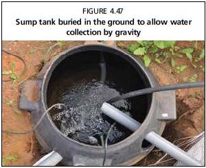
The sump tank is a water collection tank at the lowest point in the system; water always runs downhill to the sump (Figure 4.47). This is often the location of the submersible pump. Sump tanks should be smaller than the fish tanks, and should be able to hold between one-fourth and one-third of the volume of the fish tank. For ebb-and-flow type media beds, the sump needs to be large enough to hold at least the entire volume of water in the grow beds (see Section 4.3). External sump tanks are mainly used in media bed units; however, for DWC units the actual hydroponic canal can be used as a sump tank pump house also. Although helpful, it is not an essential system component, and many designs do not employ an external sump tank. Very small units, with fish tanks up to 200 litres can simply pump water from the fish tank to the grow beds, from where water trickles back down into the fish tank.
FIGURE 4.47
Sump tank buried in the ground to allow water collection by gravity
However, for larger units it is very useful to have a sump.
A common method of aquaponics, and the one recommended here, is to have the pump located in the sump tank. A commonly used acronym describes the key points of this design, which is: constant height in fish tank - pump in sump tank (CHIFT- PIST). Using this method means that any water losses, including both evaporation and leaking components, are only manifested within the sump tank and do not affect the volume of the fish tank. It is then straight-forward to measure the normal evaporative losses and to calculate how often water needs replenishing, and it can be determined immediately if there is a leak. Perhaps more importantly, any leaks in the hydroponic system will not harm the fish. Section 9.2 discusses securing water levels in different ways.
4.2.7 Plumbing materials
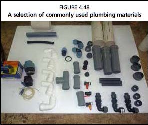
Every system requires a selection of PVC pipe, PVC connections and fittings, hoses and tubes (Figure 4.48). These provide the channels for water to flow into each component. Bulkhead valves, Uniseals® (hereafter uniseal), silicone sealant and Teflon tape are also needed. The PVC components are connected together in a permanent way using PVC cement, although silicone sealant can be temporarily used if the plumbing is not permanent and the joints are not under high water pressure. In addition, some general tools are needed such as hammers, drills, hand saws, electric saws, measuring tapes, pliers, channel-locking pliers, screwdrivers, levels, etc. One special tool is a hole-saw and/
FIGURE 4.48
A selection of commonly used plumbing materials
or spade bit, which are used in an electric drill to make holes up to 8 cm, necessary for inserting the pipes into the fish tanks and filters, as well as for making holes in the PVC or polystyrene grow beds in NFT and DWC systems. Appendix 8 contains a detailed list of materials needed for each unit described in this publication.
Make sure that the pipes and plumbing used in the system have never previously been used to hold toxic substances. It is also important that the plumbing used is of food-grade quality to prevent possible leeching of chemicals into the system water. It is also important to use pipes that are black and/or non-transparent to light, which will stop algae from growing.
FIGURE 4.49
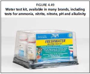
Water test kit, available in many brands, including tests for ammonia, nitrite, nitrate, pH and alkalinity
4.2.8 Water testing kits
Simple water tests are a requirement for every aquaponic unit. Colour-coded freshwater test kits are readily available, fairly economical and easy to use, and thus these are recommended. These can be purchased in aquarium stores or online. These kits include tests for pH, ammonia, nitrite, nitrate, GH and KH (Figure 4.49). Be sure that the manufacturers are reliable and that the expiration date is still valid. Other methods include digital meters or test strips. If using digital meters for pH or nitrate, be sure to calibrate the units according to the manufacturer's directions. A thermometer is necessary to measure water temperature. In addition, if there is risk of saltwater in the source water, a cheap hydrometer, or a more accurate but more expensive refractometer, is worthwhile. More details on the use of colourimetric test kits are included in Section 3.3.6.