4.5 DEEP WATER CULTURE TECHNIQUE
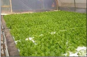
The DWC method involves suspending plants in polystyrene sheets, with their roots hanging down into the water (Figures 4.68 and 4.69). This method is the most common for large commercial aquaponics growing one specific crop (typically lettuce, salad leaves or basil, Figure 4.70), and is more suitable for mechanization. On a small-scale, this technique is more complicated than media beds, and may not be suitable for some locations, especially where access to materials is limited.
FIGURE 4.68
Illustration of a small deep water culture unit using a media bed as filtration
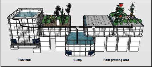
FIGURE 4.69
Illustration of a small deep water culture unit using standalone filtration
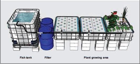
FIGURE 4.70
A large deep water culture unit
4.5.1 Water flow dynamics
The water flow dynamics in DWC are almost identical to those through an NFT. The water flows by gravity from the fish tank, through the mechanical filter, and into the combination biofilter/sump. From the sump, the water is pumped in two directions through a "Y" connector and valves. Some water is pumped directly back to the fish tank. The remaining water is pumped into the manifold, which distributes the water equivalently through the canals. The water flows, again by gravity, through the grow canals where the plants are located and exits on the far side. On exiting the canals the water is returned to the biofilter/sump, where again it is pumped either into the fish tank or canals. The water that enters the fish tank causes the fish tank to overflow through the exit pipe and back into mechanical filter, thus completing the cycle.
This "Figure 8" configuration describes the path of the water seen in the DWC system. As in the NFT, the water flows through the mechanical filter and the biofilter before being pumped back to the fish tank and the plant canals. One drawback in this configuration is that the combination sump/biofilter returns part of the effluent water from the plant canals back to the plants. However, unlike in the NFT where the nutrients in the small film of water flowing at root level quickly become depleted, the large volume of water contained in the DWC canals allows for considerable amounts of nutrients to be used by plants. Such nutrient availability would also suggest different system designs. A serial distribution of water along the DWC canals can be constructed by simply using a "cascade" configuration with only a single inlet serving the farthest tank. In this case, the outlet of one tank would be the inlet of the successive one, and the increased water flow would help the roots to access a higher flow of nutrients.
In the DWC system shown in Figure 4.68, water is pumped from the biofilter container into canals that have polystyrene sheets floating on top supporting the plant. The flow rate of the water entering each canal is relatively low. Generally, every canal has 1-4 hours of retention time. Retention time is a similar concept to turnover rate, and refers to the amount of time it takes to replace all the water in a container. For example, if the water volume of one canal is 600 litres and the flow rate of water entering the container is 300 litres/h, the retention time would be 2 hours (600 litres ÷ 300 litres/h).
4.5.2 Mechanical and biological filtration
Mechanical and biological filtration in DWC units is the same as in NFT units which is described in Section 4.4.2.
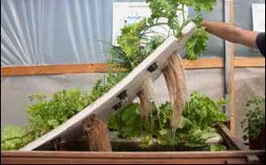
FIGURE 4.71
A small-scale deep water culture aquaponic unit. Plant roots visible below the polystyrene raft
4.5.3 DWC grow canals, construction and planting
Canals can be of variable lengths, from one to tens of metres (Figure 4.71). In general, their length is not an issue, as seen in the NFT, because the large volume of water enables adequate nutrient supply. Optimal plant nutrition in very long canals should always allow for adequate water inflow and re-oxygenation to ensure that nutrients are not depleted and that roots can breathe. As far as the width is concerned, it is generally recommended to be the standard width of a sheet of polystyrene, but it can be multiples of this. However, narrower and longer canals enable a higher water speed that can beneficially hit the roots with larger flows of nutrients. The choice of width should also consider accessibility by the operator. The recommended depth is 30 cm to allow for adequate plant root space. Similar to fish tanks, canals can be made out of any strong inert material that can hold water. For small-scale units, popular materials include fabricated IBC plastic containers or fibreglass. Much larger canals can be constructed using wood lengths or concrete blocks lined with food-grade waterproof sheeting. If using concrete, make sure it is sealed with non-toxic, waterproof sealer to avoid potential toxic minerals leaching from the concrete into the system water.
As mentioned above, the retention time for each canal in a unit is 1-4 hours, regardless of the actual canal size. This allows for adequate replenishment of nutrients in each canal, although the volume of water and the amount of nutrients in the deep canals is sufficient to nourish the plants over longer periods. Plant growth will definitely benefit from faster flow rates and turbulent water because roots will be hit by many more ions; whereas slower flows and almost stagnant water would have a negative impact on plant growth.
FIGURE 4.72
Air stone used inside a deep water culture canal
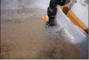
Aeration for DWC units is vital. In a densely planted canal, the oxygen demand for plants can cause DO levels to plummet below the minimum. Any decomposing solid waste present in the canal would exacerbate this problem, further diminishing DO. Thus, aeration is required. The simplest method is to place several small air stones in the canals (Figure 4.72). The air stones should release about 4 liters of air per minute, and be arranged every 2-4 m2 of canal area. In addition, Venturi siphons (see Section 4.2.5) can be added to the water inflow pipes to aerate the water as it enters the canal. Finally, the Kratky method of DWC can be used (Figure 4.73). In this method, a space of 3-4 cm is left between the polystyrene and the water body inside the canal. This allows air to circulate around the top section of the plant roots. This approach removes the need for air stones in the canal as sufficient amounts of oxygen in the air are supplied to the roots. Another advantage of this method. is the avoidance of direct contact of the plant
FIGURE 4.73 An illustration of the Kratky method for deep water culture showing the separation between the raft and the water surface
FIGURE 4.74 Polystyrene sheet in a small deep water culture unit showing planting holes
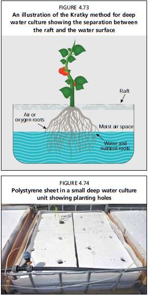
stems with water, which reduces the risks of plant diseases at the collar zone. Moreover, the increased ventilation as a result of the increased air space favours heat dissipation from water, which is ideal in hot climates
Do not add any fish into the canals that could eat the plant roots, e.g. herbivorous fish such as tilapia and carp. However, some small carnivorous fish species, such as guppies, mollies, or mosquito fish, can be used successfully to manage mosquito larvae, which can become a huge nuisance to workers and neighbours in some areas.
The polystyrene sheets should have a certain number of holes drilled to fit the net cups (or sponge cubes) used for supporting each plant (Figure 4.74). The amount and location of the holes is dictated by the vegetable type and the distance desired between the plants, where smaller plants can be spaced more closely. Appendix 8 includes specific details and helpful hints on how to drill the holes.
Seedlings can be started in a dedicated plant nursery (see Section 8.3) in soil blocks or a soil-less medium. Once these seedlings are large enough to handle, they can be transferred into net cups and planted into the DWC unit (Figure 4.75). The remaining space in the net cup should be filled with hydroponic media, such as volcanic gravel, rockwool or LECA, to support the seedling. It is also possible to simply plant a seed straight into the net cups on top of the media. This method is sometimes recommended if vegetable seeds are accessible because it avoids the transplant shock during replanting. When harvesting, be sure to remove the whole plant, including roots and dead leaves, from the canal. After harvest the rafts should be cleaned but not left to dry so as to avoid killing the nitrifying bacteria on the submerged surface of the raft. Large scale units should clean the rafts with water to remove dirt and plant residues and immediately repositioned in the canals to avoid any stress to the nitrifying bacteria.
FIGURE 4.75
Step by step procedure of placing a seedling and gravel (a) into a net cup (b) and placing it into the polystyrene raft in the deep water culture unit (c)

4.5.4 Special case DWC: low fish density, no filters
Aquaponic DWC units can be designed that do not require external additional filtration (Figure 4.76). These units carry a very low stocking density of fish (i.c. 1-1.5 kg of fish per m3 of fish tank), and then rely mainly on the plant root space and interior area of the canals as the surface area to house the nitrifying bacteria. Simple mesh screens capture the large solid waste, and the canals serve as settling tanks for fine waste. The advantage to this method is the reduction in initial economic investment and capital costs, while at the same time eliminating the need for additional filter containers and materials, which can be difficult and expensive to source in some locations. However, lower stocking densities will lead to lower fish production. At the same time, many aquaponic ventures make the vast majority of their profits on the plant yield rather than the fish production, essentially only using the fish as a source of nutrients. Often, this method requires nutrient supplementation to ensure plant growth. If considering this method, it is worth to assessing the desired fish and plant production and considering the relative costs and gains.
FIGURE 4.76
Illustration of a small deep water culture without a mechanical solid separator or biofilter
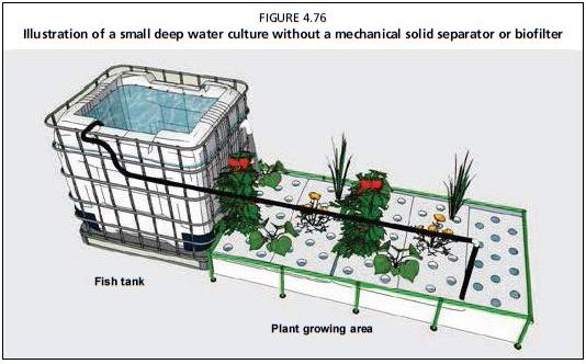
The main difference between the two designs (high fish stocking vs. low fish stocking) is that the low-density design does not use either of the external filtration containers, mechanical or biological. Water flows by gravity from the fish tank straight into DWC canals, passing through a very simple mesh screen. Water is then returned either to a sump and pumped back to the fish tanks, or directly to the fish tanks without a sump. Water in both the fish tanks and canals is aerated using an air pump. The fish waste is broken down by nitrifying and mineralizing bacteria living on the plant root surface and the canal walls.
The fish stocking density is a continuum, stretching from very low densities that do not need filters all the way up to very high densities that need dedicated external filters. One simple solution to procure additional mineralization and biofiltration and to avoid waste accumulation of solids at the bottom of the canals consists in combining the simple mesh screen with a basket of pea gravel or clay balls positioned just above the water level where the water exits the fish tank. The basket would act as a trickling filter with its med ia trapping and mineralizing the solids. The water falling from the basket would also add oxygen through its splash effect. In addition, the use of pea gravel would have a buffering action against water acidification following nitrification. Another option can include an internal biofilter within the fish tank, consisting of a simple mesh bag of biofilter material near an air stone. This can help to ensure adequate biofiltration without adding to the cost of external biofilters. Finally, increasing the overall water volume without increasing the fish stocking density, basically using large fish tanks for few fish, can help to mitigate water quality issues by diluting wastes and ensuring adequate time for the farmer to respond to changes before the fish become stressed, though this can dilute the available nutrients and hinder vegetable growth.
The lower fish density also means that the water flow rate can be lower. A smaller pump can be used, reducing the cost, but ensure that at least half of the total fish tank volume is exchanged per hour. In fact, some researchers have had success with removing the electric pump all together and relying on manual labour to cycle the water twice per day. However, these systems are utterly dependent on adequate aeration. Other than these differences, the recommendations for fish tanks and DWC canal construction are applicable for this low stocking density method.
Low stocking density unit management
The major difference from the management of the other units, discussed in more detail in Chapter 8, is the lower stocking density. The suggested stocking density for these types of systems is 1-5 kg/m3 (compare to 10-20 kg/m3 for other systems in this manual). Previously, it has been suggested that the balance between fish and plants follows the feed rate ratio, which helps to calculate the amount of fish feed entering the system given a set growing area for the plants. These low stocking density units still follow the suggested daily feed rate ratio of 40-50 g/m2, but should be towards the lower end. A useful technique is to allow fish to feed for 30 minutes, 2-3 times per day, and then remove all uneaten food. Overfeeding will result in an accumulation of waste in the fish tanks and canals, leading to anoxic zones, poor growing conditions, diseases, and fish and plant stress. Always, but especially when using this method without filters, be sure to monitor water quality conditions closely, and reduce feeding if high ammonia or nitrite levels are detected.
Advantages and disadvantages of low stocking density
The major advantage is a simpler unit. This system is easier to construct and cheaper to begin, having lower capital costs. The fish are less stressed because they are grown in more spacious conditions. Overall, this technique can be very useful for initial projects with low capital. These systems can be very useful for growing high-value fish, such as ornamental fish, or specialty crops, such as medicinal herbs, where the lower production is compensated with higher value.
However, a serious disadvantage is that these units are hard to scale up. Fewer plants and fish are grown in a given area, so they are less intensive than some of the systems previously outlined. In order to produce a large amount of food, these systems would become prohibitively large. Essentially, the external mechanical and biofilters are what allow aquaponics to be very intensive within a small area.
Furthermore, fish production cannot function independently from the hydroponic component; plants must be in the canals at all times. The plant roots provide the area for bacteria growth, and without these roots the biofiltration would not be sufficient to keep the water clean for the fish. If it were ever necessary to harvest all the plants at once, which can occur during disease outbreaks, season changes or major climate events, the reduced biofiltration would cause high ammonia and fish stress. On the other hand, with external mechanical and biofilters the fish production can continue without the hydroponics as a standard RAS.