PREPARING THE FISH
1. PREPARING THE FISH TANK (SAME AS MEDIA BED SECTIONS 1 AND 2).
2. PREPARING THE MECHANICAL SEPARATOR AND BIOFILTER (SAME AS NFT UNIT SECTIONS 1-4).
3. MAKING 3 DWC CANALS FROM 2 IBC TANKS (SAME AS MEDIA BED SECTION 4).
4. INITIAL STEPS IN BUILDING A DWC SYSTEM
Follow the steps contained in the previous sections to set up the fish tank, the mechanical separator, the biofilter and 3 DWC canals from 2 IBCs. Once completed, proceed to assembling the DWC canals. For the DWC system, the cut IBC bed used as a sump tank in the media bed unit can be used as the 4th canal. Extra blocks and plumbing are required to install the 4th canal.
5. ASSEMBLING THE DWC CANALS
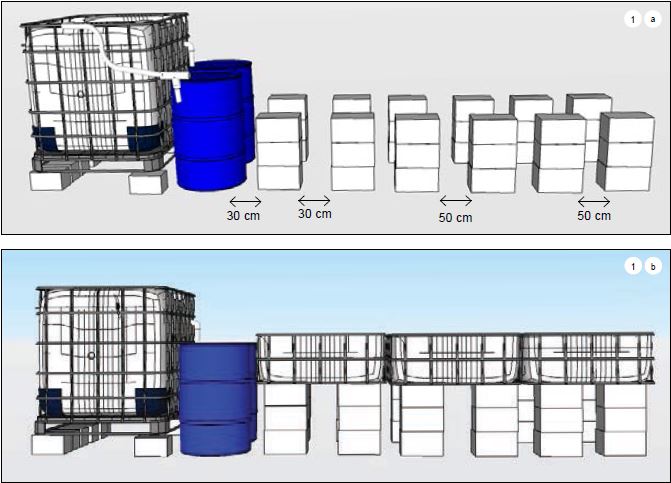
5.1 - Place the concrete blocks according to the distances described in Figure 1a. The fish tank should be raised up about 15 cm; do so by using concrete blocks. Then, place the three grow beds (including the metal support frames) on top of the blocks as shown in (Figure 1b) (Make sure the grow beds are secure on top of the blocks. If not, slightly adjust the layout of the blocks underneath).
PREPARING THE DRAINAGE PIPES INTO THE BIOFILTER The following materials are needed to make three drainage pipe units:
24 cm of PVC pipe (25 mm) x 3
• Barrel connectors (25 mm) x 3
• PVC adaptor, female (1 inch - 25 mm) x 3 • PVC elbow, female (1 inch - 25 mm) x 1
• PVC T-connector (25 mm – 1 inch {female} – 25 mm) x 2
• Rubber washer (25 mm) x 3
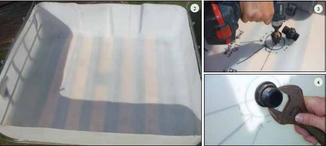
6.1 – Take each DWC canal and mark their centre points in the bottom of the canal. Drill a 25mm diameter hole at each centre point and insert the 25mm barrel connector (25mm) with the rubber washer placed inside the grow bed. Tighten both sides of the connector using a wrench (see Figures2–4).
6.2 – Screw the PVC adapter, female (1 inch – 25 mm) on to the barrel connector (25mm) inside the tanks and then slot the standpipe into the adapter. Make sure to cut five longitudinal slots on the upper end of the standpipe to prevent the pipe from clogging (Figures5–6).

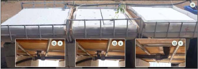
6.3 – Next, connect the PVC elbow, female (25mm – 1inch) to the end of the barrel connector underneath the DWC canal that is farthest from the fish tank (Figures7–10). Then fix the remaining two PVC T connectors (25mm – 1inch [female] – 25mm) to the barrel connectors underneath the other two canals. Take three pieces, each 1m in length, of PVC pipe (25mm) and connect the elbow to the two T-connectors underneath the canals (Figures11 and 12).

Connection between canals A, B and C
6.4 – Finally, drill a 25mm hole into the side of the biofilter barrel using the circular drill bit at least 15 cm below the standpipe height in the canals and insert a barrel connector (1inch) in it. Then, connect a PVC elbow (25mm – 1inch) to the barrel connector and then take one more piece of PVC pipe (25 mm) and connect the PVC elbow (25mm – 1inch) where it exits the biofilter to the final T-connector underneath the tank A and slot the other into the 25 mm hole in the biofilter (Figures13 and 14).
7. ADDING THE SUBMERSIBLE PUMP For this unit, the submersible pump is placed at the bottom of the biofilter barrel (Figures15 and 16).

7. ADDING THE SUBMERSIBLE PUMP
For this unit, the submersible pump is placed at the bottom of the biofilter barrel (Figures15 and 16).

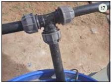
Water is pumped from there into two locations: the 3DWC canals and the fish tank. 80percent of the water flows to the fish tank while 20percent flows into the plant canals. The taps are used to control the water flow at each location (Figure17).
8. PUMPING TO THE FISH TANK AND DWC CANALS
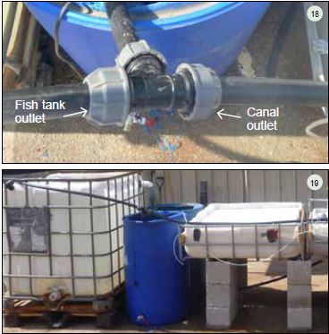
8.1 - Connect the submersible pump to a length of polyethylene pipe (25 mm) pipe length using an adaptor (1 inch female - 25 mm), or any other connection that fits to the pump. The pipe should be at least 1 m long. Place a T-connection (25 mm) at the end of the pipe allowing water to flow to the fish tank and the canals (Figure 18).
8.2 - Attach a pipe (25 mm) to one end of the T-connection long enough to reach the fish tank. Use flexible pipe if possible as this removes the need for elbow connections, which reduce the pumping capacity of the pump (Figure 19). Attach a tap (25 mm) to the end of the pipe to control the water flow into the fish tank.
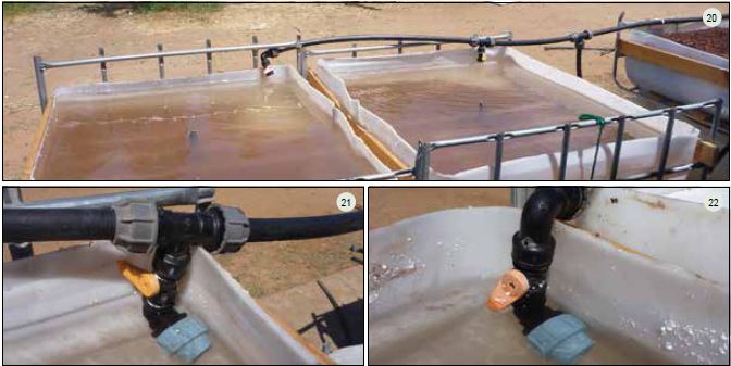
8.3 - Next, take about 3.5 metres of polyethylene pipe (25 mm) and attach one end to the remaining exit of the T-connection (25 mm) coming from the pump in the biofilter. Then, take the 3.5 metre pipe and lay it along the DWC canals. At each canal, add a T-connector (25 mm - 4 inch - 25 mm), a tap (4 inch male – 1⁄4 inch female), and a PVC elbow (25 mm - 4 inch male) allowing water to flow into each canal at an angle (Figures 20-22). At the final canal furthest from the fish tank use a PVC elbow (25 mm - 4 inch female) instead of the T-connector. Be sure to secure the pipes to the metal frame by means of plastic cable ties.
9. INSTALLING THE AIR PUMP AND STONES
9.1 – For this unit, the air pump is used to integrate air into the DWC canals. The air pump should be placed into a protected box at the highest point in the system (ideally attached to the side of the fish tank) (Figure25). Take 4–6m of 8mm air pipe. Attach one end to the air pump and lay the rest of the 8 mm pipe along the side of all the DWC canals. On each tank, drill an 8mm hole just below (1–2cm) the top and slot the 8mm pipe into each hole.
9.2 – Attach the air stones to the 8mm pipe and place them next to the inlet water stream to ensure full oxygen saturation in the canal. Repeat the same air pipe connection for the fish tank (Figures23, 24 and 26).

9.3 - Connect the pipes to the metal frame with plastic cable ties.
10. MAKING THE RAFTS
Key principles and rules of thumb for making the polystyrene rafts:
- All water in the canals should be fully covered (no exposure to light).
- Choose polystyrene sheets that are at least 3 cm thick to hold the weight of the vegetables.
- The polystyrene must not release any toxins to the water (make sure it is safe for food production or food-grade quality). Painted plywood can also be used.
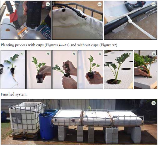
- Plant hole sizes and spacing are dependent on the type of vegetables to be planted. The planting hole size can range from 16 mm (for planting seedlings directly into the rafts without cups [Figure 28]) to 30 mm. This depends on the size of net cups available (Figure 27).

10.1 – Place the polystyrene on top of the DWC canals and mark the edge lines. With a knife, cut the outline of the canal (Figures29–31).

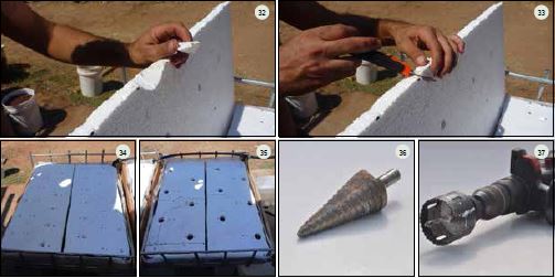
10.2 – Drill the plant holes (Figures 34 and 35) using a circular drill bit (Figures 36 and37). Along with planting holes, make sure to cut one hole for the standpipe of each canal (Figures32 and 33).
11 FINAL CHECKS
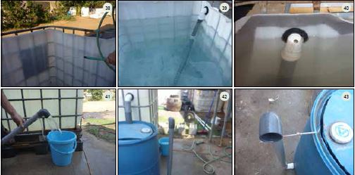
Once all parts of the system are in place, fill the fish tank, both filters and DWC canals (Figures 38-43) with water and run the pump to check for any leaks in the system. If leaks appear, fix them immediately where they arise by:
⚫ Tightening the plumbing connections.
• Checking all uniseals and taps for both filters. Re-applying Teflon to threaded connections.
• Making sure all valves are in their ideal position.
Secure all the remaining pipes with plastic cable ties (Figures45–46).
Finally, check the flow rates of the water flowing into each DWC canal. Knowing that
the volume of each canal is about 300litres, the ideal flow rate for each canal should be
75–300litres per hour according to the 1–4hour residency time mentioned in Chapter4
of this publication. Water inflow can be measured by using a stopwatch and an empty
1 litre plastic bottle (Figure 44) At 75 litres/hour the 1 litre bottle should fill up in
48seconds, at 300litres/hour in 12seconds. Once all the leaks are fixed and the water
is flowing through all components of the unit, begin cycling the unit by using ammonia to stimulate nitrifying bacteria colonization (see Chapter5 of this publication).
