3. Mooring and grid system installation
Farm installation requires specific technical skills and a high level of specialization of the staff engaged. In most cases, the installation work benefits from the help of external qualified diving or marine engineering companies.
The first step is to identify an adequate area of land to use for staging and storage, ideally close to the farm site identified.
This phase includes developing a working relationship with the authorities (harbour and/or municipal) and obtaining the necessary authorizations (for the occupancy of public area, for moving loads and for towing some components from the harbour to the farm site).
The free area on land should have the following characteristics:
? a surface large enough to allow the construction of the cage and the use of a forklift, access to electricity;
potential to leave materials and equipment safely without running the risk of theft (if possible, in a locked storehouse).
Sites meeting these requirements can be found in most port areas. A shaded area should be provided for nylon equipment (nets, ropes, etc.) in case a prolonged stocking is expected before installation (ultraviolet [UV] radiation degrades nylon).
All the farm components, equipment, gear and necessary materials will be stocked in this area, where one may work more readily than on a boat or underwater. Cage components need to be assembled on land, and they require a great deal of space.
NAVIGATIONAL BUOYS
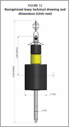
Usually, the first components that are installed are the marker buoys that designate the farm perimeter as per the licence. One mark er buoy is placed on each corner of the farm site (Figure 12).
Technical characteristics
A wide range of navigational buoys are available on the market, including both hot-dip galvanized steel and rotomoulded polyethylene. A generic component list of a navigational buoy system includes:
Concrete blocks: One of these anchors is used for each buoy, with a weight appropriate for the buoy depending on buoyancy and site characteristics, equipped with at least an 18 mm steel ring for attachment.
? Galvanized steel connecting chain: The chain connects the concrete block to the buoy, and should have a length 1.5 times the site depth and a diameter appropriate to the size of the buoy. Shackles: Two shackles are needed for each buoy; one to connect the chain to the concrete block, and the other to connect the chain to the buoy.
FIGURE 12
Navigational buoy technical drawing and dimensions (Unit: mm)

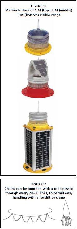
FIGURE 13
Marine lantern of 1 M (top), 2 M (middle) 3 M (bottom) visible range
FIGURE 14 Chains can be bunched with a rope passed through every 20-30 links, to permit easy handling with a forklift or crane
Swivel: The buoy should be free to rotate around its own axis.

Navigational buoy: The buoy should be highly visible, and equipped with a radar-reflector device and marine lantern.
Modern marine lanterns (Figure 13) are equipped with several light-emitting diode (LED) lights, which provide bright lights with minimal power usage. They should be bright enough to be seen from a long distance, as required by local regulations. These types of lanterns usually have solar panels to recharge the batteries and are relatively maintenance-free.
Navigational buoys are generally yellow, but some regions require special cardinal buoys in which each buoy has a different colour sequence in order to be easily recognized.
Material assembly on land
The buoy assembly (concrete block, shackle, chain, shackle and buoy) should be prepared on land.
One end of the chain is connected with a shackle to the buoy's pad eye on the lower part of the buoy.
Both the buoy with the chain and the concrete block are loaded on board the vessel. The free end of the chain is connected to the concrete block's pad eye with a shackle.
Chain can be bulky and unwieldy to handle. One method for easier handling is to bundle the chain by passing a stout rope through every 20-30 links as shown in Figure 14, resulting in numerous coils, which reduces the chain's length. This method can be used for any chain deployments discussed in this manual.
Deployment
Once at the deployment point (determined with the aid of a GPS) the rope keeping the chain "bunched" is removed. The next steps are:
The buoy is craned into the water, and the boat begins to move forwards, towing the buoy. Once at the exact point for deployment, the chain is deployed overboard, the concrete block is lifted up by the crane's hook using a rope sling, and held out over the water. The rope sling is cut. The concrete block will sink until the buoy is in position (Figure 15).