GRID SYSTEM AND MOORING SYSTEM
The mooring system used with the HDPE circular cages is a square-shaped grid system held on the sea bed with an array of mooring lines.
It is a dynamic system; all of the components keep the structures moored to the sea bed, and are designed to dampen the forces generated by the wave motion.
The mooring system is divided in two main groups of components, the mooring lines and the grid system (Figure 16):
The mooring lines include the anchors, ground chains, ropes and related shackles, and buoys. The grid system includes the frame ropes, mooring buoys, connector rings or plates, bridles, and related shackles.
In a grid system, the cages are not moored separately one from the other, but are instead aggregated in modules.
The most common modules in offshore sites are composed of 6, 8 or 12 cages, installed in two parallel columns. Larger modules are also used in sheltered sites, including some larger systems of up to 36 cages in a 3 x 12 grid system, but there may be concerns on the possible oxygen availability and total loads on the mooring components.
Six or eight unit grid systems are preferable in exposed sites with strong currents and waves.
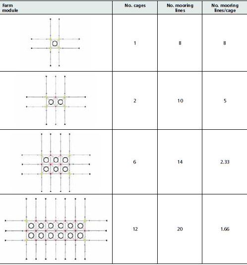
System design depends on the number of cages that will be moored, as well as the number of mooring lines. The ratio between the number of cages and number of moorings is a useful indication of how securely the cages are moored as well as of the relative cost. A farming module with a smaller number of cages will have a relatively higher number of mooring
FIGURE 15
Navigational buoy mooring scheme: the buoy is moored to a concrete block by a chain. A portion of the chain should lie on the sea bed to permit the vertical movement of the buoy with the waves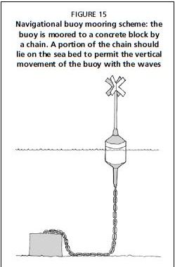
FIGURE 16
Grid system and mooring lines in a framing module of six cages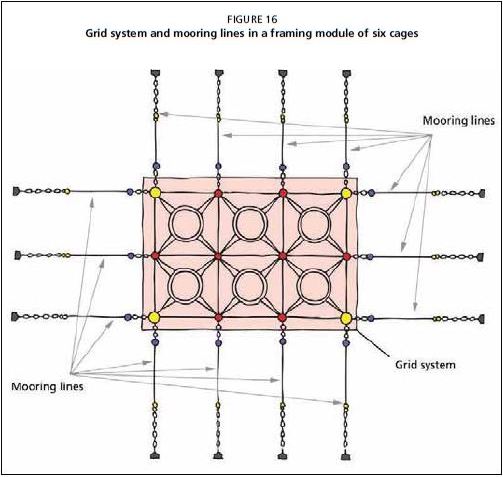
lines per cage (Table 10). This is preferred in a highly exposed site because a greater number of anchors will hold each cage more securely. On the other hand, in a sheltered site larger modules can be used where the mooring system would benefit from an economy of scale, requiring relatively fewer anchors and subsequent lower installation costs. Table 10 is a guide and additional mooring lines can be added as required to reinforce the farming module, particularly those situated in exposed sites.
If the grid system has more than eight cages, the forces generated by current or waves may strain the grid, causing it to sag in the middle (Figure 17). For this reason, if it is not possible to reduce the number of cages, the central mooring lines should be doubled and cross-linked, i.e. requiring the installation of additional anchors (Figure 18).
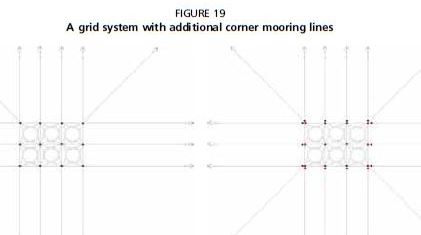
Furthermore, in order to reinforce the corner points of the grid system it is possible to install “corner anchors” on one or more sides (Figure 19). These additional mooring lines reduce stress on the grid corners caused by the currents and waves flowing in from those directions.
The mooring system can be installed using single or double mooring buoys. The first option is mainly used with a floating cage system, while the second option is used with submersible cages or in case of high-energy sites. In the case of a submersible cage
TABLE 10
Square grid systems showing different number of cages and mooring lines (if no additional mooring lines are added to reinforce the system)
system, the submerged cages use the grid as a hanging frame while submerged, so a double line of mooring buoys is needed (the first on the mooring lines, and the second on the grid corners). The double-mooring buoy system could also be used with large cages, or in high-energy sites where additional buoyancy is necessary.
FIGURE 17
A grid system deformed by forces generated by current or waves
FIGURE 18
A grid system with the central mooring lines doubled
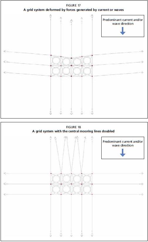
FIGURE 19
A grid system with additional corner mooring lines
Schematics and details of a double buoy mooring system are presented in Appendix 1.
Farm footprint
The actual surface area occupied by a cage farm system is called the farm footprint (Figure 20).
The total area of an HDPE cage system is much larger than the visible floating components.
The floating components (buoys and cages) will occupy the smaller area of the grid system, while a much larger area underwater will be occupied by the mooring lines.
FIGURE 20
Surface area occupied by a cage farm system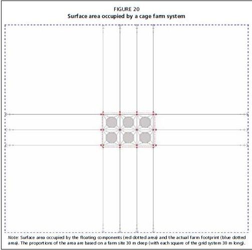
Note: Surface area occupied by the floating components (red dotted area) and the actual farm footprint (blue dotted area). The proportions of the area are based on a farm site 30 m deep (with each square of the grid system 30 m long).
This is important in evaluating the licence or lease area dimensions, and the safety “no fishing zone” around the licensed area.
To calculate this footprint, a mooring line length of at least 4–4.25 times longer than the site depth should be used. This is because the maximum loading power of anchors is generated by the angle of 9–12° between the anchor and the mooring line. Thus, the dimensions of the grid system, plus 4–4.25 times the depth of the site (for each side of the grid system) will give the actual dimensions of the footprint.
Mooring and grid components
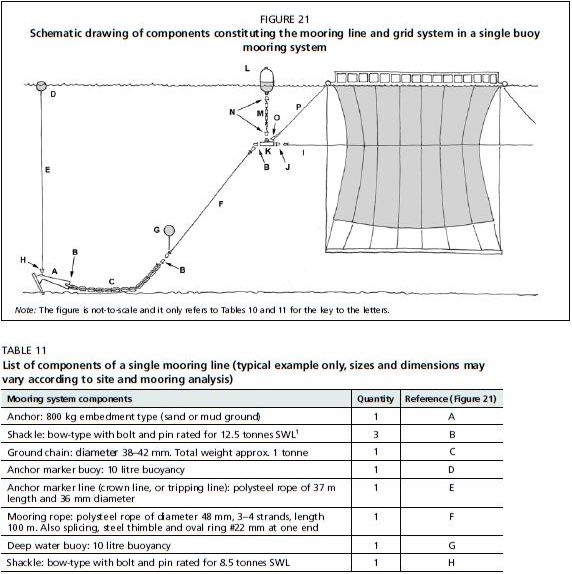
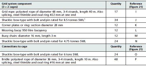
The components of a single mooring line are detailed in Table 11, with components for a grid system presented in Table 12. In both these tables, a reference to Figure 21 is provided for each component.
The sizes of the components are for a 3 ? 2 grid system module, with cages of 20 m in diameter in a medium-energy site (Hs 2.5 m), 25 m deep.
Is recommended that all the components of the mooring system must be certified by the supplier for the declared Safe Working Load (SWL).
FIGURE 21
Schematic drawing of components constituting the mooring line and grid system in a single buoy mooring system
TABLE 11
List of components of a single mooring line (typical example only, sizes and dimensions may vary according to site and mooring analysis)
1 SWL = safe working load.
Note: The total number of components required is obtained by multiplying the quantities below by the actual number of mooring lines (see also Table 10).
TABLE 12
List of equipment for a 3 ? 2 cages grid system (typical example only, sizes and dimensions may vary according to site and mooring analysis)
1 SWL= safe working load.
Note: Tables 11 and 12 are only to be used as a reference. Size and dimensions of all components must be properly calculated according to the actual characteristics of the farm site selected.
Lengths of the mooring lines in the tables are only suitable for a site with a water depth of 25 m. The total length of a mooring line must be at least 4–4.25 times the site depth, or longer if specified by the cage supplier. The size of each component must be properly calculated, according to site characteristics, cage size and cage design.
Mooring points
Different types of anchors are suited to various types of substrate. Plate 2 shows multipurpose anchors used for sandy or muddy bottoms. These are the most commonly used anchors in farm mooring (Figure 22). In the event of rocky sea bottoms or unsuitable environmental conditions of the site, rock pins may be considered as mooring points in case anchors or concrete blocks (see below) cannot be employed (Plate 3).
PLATE 2
Plough anchors
COURTESY OF: A. CIATTAGLIA
PLATE 3
A rock pin fixed to a rocky shore
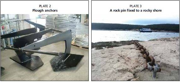
The holding capacity for these anchors ranges from 20 to more than 50 times the weight, when installed in mud-silt or compacted sand.
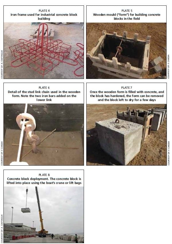
Alternatively, or in combination with the anchor, concrete blocks can be installed (Plates 4–8). As a mooring, the weight of concrete must be proportional to the drag forces to which it is subjected. These anchors can range in weight from several hundred kilograms to 10–20 tonnes.
In some cases, a concrete block may include a through-hole for the insertion of a safety chain for lifting and manoeuvring of the block, and for additional safety in the mooring. The upper steel ring will generally be 30–40 mm thick and is subjected to heavy abrasion by the continuous friction of the mooring shackle. If the ring fails, the safety chain can still hold the mooring in place.
The shape of the concrete block is also important. A broader concrete profile is always preferable to a narrower footprint, to improve adhesion to the sea bed. If the block has a convex bottom, it will increase the adhesive power to the sea bed by creating a suction effect, particularly in soft sand or muddy substrates.
FIGURE 22
Example of plough anchors – technical drawing and dimensions
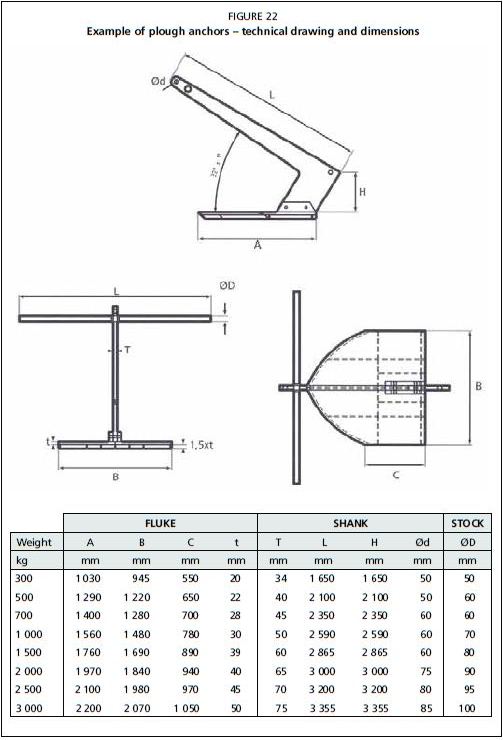
PLATE 4
Iron frame used for industrial concrete block building
Wooden mould ("form") for building concrete blocks in the field
PLATE 6
Detail of the stud link chain used in the wooden form. Note the two iron bars added on the lower link
PLATE 7
Once the wooden form is filled with concrete, and the block has hardened, the form can be removed and the block left to dry for a few days
PLATE 8
Concrete block deployment. The concrete block is lifted into place using the boat's crane or lift bags
COURTESY OF: E CARDIA
PLATE 5
COURTESY OFF. CARDIA
COURTESY OF: A. CIATTAGLIA
COURTESY OF: E CARDIA
COURTESY OF A CIATTAGLIA
Chains
Two different types of chains are used in cage aquaculture: stud less chains and stud link chains. The two types differ by the presence (stud link) of a stud in the centre of each link (Figure 23).
The size of a chain is commonly indicated using the diameter of the section of the link expressed in millimetres (mm), O in Figure 23. In this manual, this value is used to indicate a chain size.
Stud less chains are mostly used as connection elements between mooring components, such as buoys and corner plates or rings of the grid system. In these cases, the link diameter does not usually need to exceed 14-16 mm.
New chains, of high-strength steel (such as
grade 60 or 80), are recommended. Table 13 provides some technical specifications of studless chains of different diameters.
TABLE 13
Characteristics of studless chains (indicative)
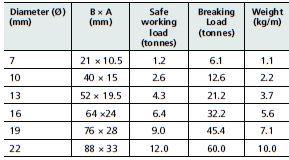
FIGURE 23
Studless and stud link chains (O = diameter
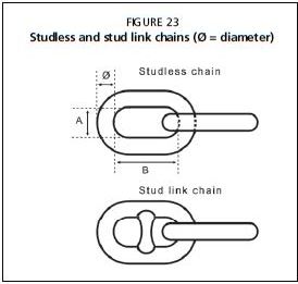
TABLE 14
Stud link chains: weight per metre (indicative)
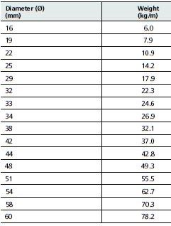
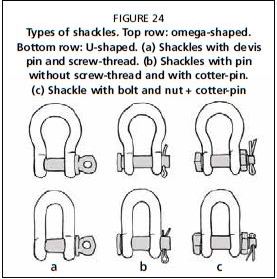
FIGURE 24
Types of shackles. Top row: omega-shaped. Bottom row: U-shaped. (a) Shackles with clevis pin and screw-thread. (b) Shackles with pin without screw-thread and with cotter-pin. (c) Shackle with bolt and nut + cotter-pin
Stud link chains have a higher safe working load (SWL) and are commonly heavier than studless chains, given equal length and (see. Tables 13 and 14).
The ground chain is usually of a stud link type. It is often tarred to ensure it lasts longer int the marine environment. The size can range from 38 to 42 mm thickness (with a weight of about 30-35 kg/m), up to 50 mm (with a weight of about 50-60 kg/m).
The ground chain, connecting the anchor and the mooring rope is primarily used to provide weight to the mooring line, in order to keep the angle between seafloor and the mooring line within the desired range, between 9° and 12°.
Shackles
Shackles are used to connect mooring ropes, chains and anchors (Figure 24).
The SWL capacity in tonnes is usually used to identify the size of shackles.
Shackles can be U-shaped or omega-shaped (Figure 24). Omega-shaped shackles are the most common because they can accommodate a greater number of connections.
Shackles can be locked with one of the. following main systems:
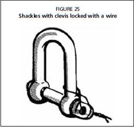
clevis pin and screw-thread, where the pin is locked with a wire or welded shut to prevent the nut from loosening (Figure 24a and Figure 25).
?round pin without screw-thread, but with a cotter-pin (Figure 24b).
bolt and nut + cotter-pin, to prevent the loosening of the nut (Figure 24c).
Stainless steel cotter-pins are strongly recommended.
The second locking system described above is the less preferred for mooring connections, as the cotter-pin may corrode as a result of the galvanic current generated in the system.
FIGURE 25 Shackles with clevis locked with a wire
Deep water buoys
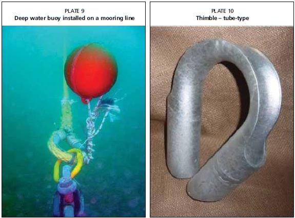
The deep water buoys are made with a rigid material based on polyethylene or polyvinyl chloride (PVC). These components are used to lift the connection point between the chain and rope in the mooring line to a void abrasion of the line when it comes in contact with the sea bed (Plate 9).
These floats can also be used as anchor markers at the surface end of the tripping line.
Thimbles
Thimbles are generally made of hot-dip galvanized steel, and are used to reinforce the rope loop (eye splice) where it is connected to metal equipment (shackles, rings, etc.), and thus where it is subjected
to heavy abrasion. Thimbles can markedly reduce wear on the rope.
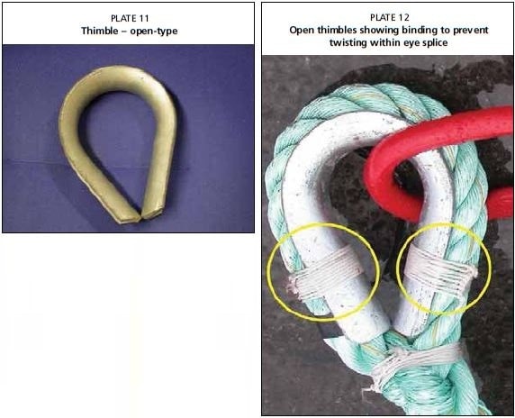
Thimbles used for moorings are usually either "tube-type" or "open-type" (Plates 10 and 11).
Tube-type thimbles reduce the possibility of the splice becoming undone over time, and provide more protection to the spliced rope. However, they are heavier and more expensive.
Thimbles are fixed to the rope through an eye splice. Splicing is a knotting procedure that provides for minimal loss of rope tensile strength. Each knot weakens the rope. A simple knot can reduce the effective breaking load of a rope by 55 per cent compared with the original rope specifications, while a splice results in a reduction of only 5 percent (Prado, 1990). In a mooring line eye-splice, the rope strands are braided back
PLATE 9 Deep water buoy installed on a mooring line
PLATE 10 Thimble-tube-type
COURTESY OF: F CARDIA
COURTESY OF: A. CIATTAGLIA
PLATE 11 Thimble open-type
PLATE 12
Open thimbles showing binding to prevent twisting within eye splice
COURTESY OF: F. PICCOLOTTI
COURTESY OF: A CIATTAGLIA
upon themselves at least four times, to provide the greatest splice strength.
Open thimbles should be fixed with two bindings, as shown in Plate 12. This will avoid thimble rotation inside the eye loop once the rope becomes stretched under load.
Corner plates
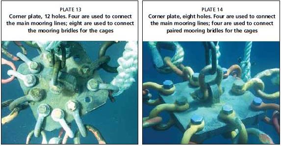
Corner plates are used to connect the different parts of the grid system. They come in many shapes and sizes. Mooring plates are the main connecting points of the whole grid structure
where all components come together and are locked with shackles: the grid system, the mooring lines, the buoy chains and the cage bridles (Plates 13 and 14).
Plates are usually square-shaped, with sufficient holes for the shackle pins to be inserted. At times, steel rings are used instead of corner plates as shown in Plate 15 (see next section).
PLATE 13
Corner plate, 12 holes. Four are used to connect the main mooring lines; eight are used to connect the mooring bridles for the cages
PLATE 14
Corner plate, eight holes. Four are used to connect the main mooring lines; four are used to connect paired mooring bridles for the cages
COURTESY OF: AD.AQ. SRL
COURTESY OF: A. CIATTAGLIA
PLATE 15
A steel ring used in a mooring grid in place of a corner plate
PLATE 16
Circular steel ring used as connecting element in the grid system
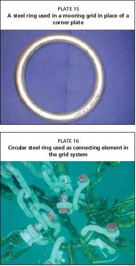
PLATE 17 Elliptical steel ring
PLATE 18
Steel rings used for connecting eye spliced ropes with thimbles through a pair of shackles. Another shackle then connects the circular ring to the corner plate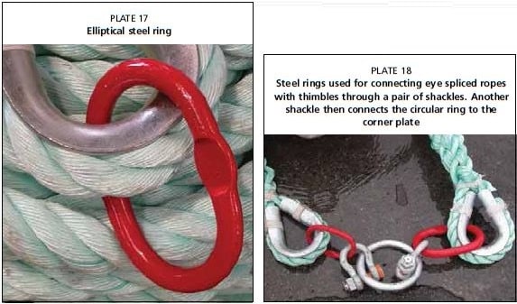
COURTESY OF: A. CIATTAGLIA
Steel rings
Hot-dip galvanized steel rings are used at intersections in the mooring system. Round- shaped rings are used where different grid-lines intersect (Plate 16).
Oval-shaped or elliptical rings (Plate 17) are inserted into steel thimbles in order to avoid using larger more expensive elements (e.g. shackles and thimbles) when connecting elements of similar breaking loads. Plate 18 shows connections within the mooring array.
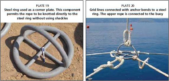
Mooring systems without shackles are sometimes used in sheltered sites. These systems have large iron rings (Plate 19) on the grid corners, where the grid and mooring ropes are connected through a "lark's head" or "bow anchor" knot (Plates 20 and 21). This prevents wear and tear of the metals and reduces maintenance costs. It is necessary to use only high-quality ropes that can be securely tightened; ropes made of polyester or nylon are recommended. Polysteel can be too slippery a material for these purposes.
Buoys
There is a wide range of sizes and shapes of mooring buoys available on the market (Plate 22). These are generally described by their buoyancy, expressed in kilograms or volume (in litres). The buoyancy in kilograms of a buoy is equivalent to the volume of the buoy minus its weight in kilograms.
The outer material is often rotationally moulded polyethylene, and the filling is usually polyurethane foam or polystyrene.
In most buoys, a steel bar (about 30-40 mm thickness) runs through the main buoy body to
PLATE 19
Steel ring used as a corner plate. This component permits the rope to be knotted directly to the steel ring without using shackles
PLATE 20
Grid lines connected with anchor bends to a steel ring. The upper rope is connected to the buoy connect the two opposite attachment rings and
COURTESY OF: E CARDIA
PLATE 21
add strength. More recently, full plastic HDPE Steel ring connected to grid lines and cage bridles buoys have also been produced to reduce galvanic corrosion problems.
PLATE 22
Buoys of different sizes stored on a harbour pier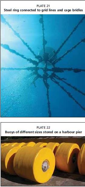
COURTESY OF: A. CIATTAGLIA
COURTESY OF: E CARDIA
COURTESY OF: N. KEFERAKIS
Ropes
Ropes are the main components of the mooring system, and are used for both the mooring lines and grid system lines.
The most common rope material used is polysteel or danline, a blend composed of polypropylene and extruded polyethylene. This combination provides a line of the same weight and price as polypropylene, but with a tensile strength more than 25 percent higher.
Polyester or nylon ropes can also be used, but these are more expensive, and have much more stretch when placed under load. Stretching in the lines can cause major problems in the mooring grid.
Mooring system installation
This section describes a possible procedure for installing a 3 x 2 cage mooring system.
Note: The following procedure is intended only as an example. Any deployment will need to consider different arrangements according to the working team, available service boat and mooring dimensions.
This example is provided considering a grid system where corner palates and shackles are used (see Plates 13 and 14); procedures for deploying grid systems with rings (see Plate 15) may have different steps and operational sequences.
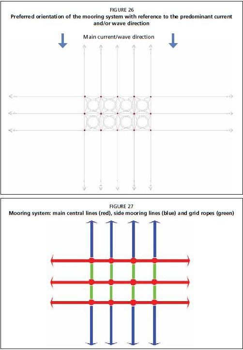
Before installation, the correct mooring system orientation must be determined. This is a critical factor for the best performance from the mooring equipment. The orientation is generally planned according to the main or dominant current and/or wave direction. If no other reasons exist, the grid should be oriented to ensure the best possible oxygen supply to the farmed fish and the largest number of mooring lines holding the farm against the predominant currents and waves (Figure 26).
To describe the mooring system installation, a six-cage module system comprised of three groups of two cages is used as an example (Figure 27):
three main central lines (red lines);
eight grid lines (green lines);
eight side mooring lines (blue lines).
FIGURE 26
Preferred orientation of the mooring system with reference to the predominant current and/or wave direction
FIGURE 27
Mooring system: main central lines (red), side mooring lines (blue) and grid ropes (green)
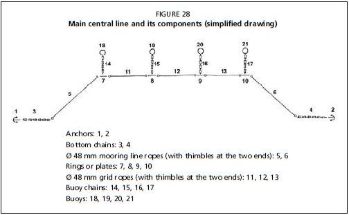
Each one of these groups will be deployed in succession and assembled together at sea. Each main central line as shown in Figure 28 will be made up of two mooring lines (components 1-3-5 and 2-4-6), plus a portion of the grid system (components 7-21). The connections among the various elements are always made through adequately sized shackles.
FIGURE 28
Main central line and its components (simplified drawing)
Assembling of components on land
The assembly work begins on land
First, the ropes must be uncoiled and unrolled in the correct manner. If a coil is unrolled without following the correct procedure, the rope will twist and knot and this can weaken the rope. The correct procedure is to place the coil on an axle or spool, so it can spin freely, and then take the bitter end of the rope (free end) in one's hands, and walk away from the coil so that it comes directly off the coil without twisting. All rope must be unrolled in this manner, including mooring lines, grid lines and bridle lines. Assembly starts by connecting the various elements of the first main central line (numbering as referred to in Figure 28).
1. The rope (5) is linked to the plate (7); then three of four plates (7-9) are connected through the grid ropes (11), (12) and (13). All the elements are then connected one to each other as in Figure 28.
In this way, a portion of main line is assembled and properly set out in a coil on a pallet. Plates (or rings) must be left outside the coil to ensure easy access.
Care must be taken to wind the line onto the pallet in reverse order so that the first element to be deployed is at the end of the coil. This ensures ease of deployment. 2. The steel plate (10) is linked to mooring rope (6) and this portion is coiled onto a second pallet.
The pallets are then loaded aboard the deployment vessel.
These are the elements that together with two anchors and their respective bottom chains will compose a main mooring line.
Similarly to point 1, the assembled components are set out in coils on a pallet.
The 12 surface buoys and their respective buoy chains are connected, and then loaded aboard the deployment vessel. The chains can be bunched with a rope, as described above for navigational buoy installation (Figure 14).
The final on-land stage consists of preparing the anchors and their respective ground chains, which will similarly be bunched.
Boat loading
The deployment vessel should ideally be equipped with a crane, with a hydraulic drum, and should have adequate haulage power. Speed is a secondary consideration.
The most important dimension characteristic of the deployment vessel is the available space on the deck. The deck will require sufficient room to load the following components:
? two anchors;
? two ballast chains;
two tripping lines;
the pallets (as described in the previous section);
surface buoys with their respective buoy chains.
The precise layout of the elements on deck is very important. Once the first anchor is deployed, it will drag out all the other elements. Therefore, each mooring component has to be free to move without becoming entangled or snagged on the boat's fittings. Once the components are placed aboard, they will be connected together, and each major line is assembled into two sections, to facilitate the deployment:
First major line section:
Connect the bottom chain (3) to the anchor (1).
Connect the tripping line with the anchor.
Connect the end of the bottom chain to the thimble of rope (5), which is on the top of the pallet with the line.
Connect the three buoy chains to the three plates, which are in view on the pallet coiled with the line.
Second major line section:
Connect the bottom chain (4) to the anchor (2).
Connect the tripping line with the anchor (2).
• Connect the end of the bottom chain to the thimble of rope (6) which is on the top of the pallet with the coiled line.
Connect the buoy chain (17) to the plate (10).
All the above connections have to be made using correctly sized shackles.
Once these operations have been completed, the first major line's components, from anchor (1) to anchor (2) are connected into two separate sections, and are ready to be. deployed.
Installation at sea
Major line installation
For the installation at sea, it is useful to employ an additional smaller boat as a support vessel to recover buoys, to retrieve lift bags and scuba divers, and to assist with the surface buoy alignment.
The mooring system must be placed in a previously determined position inside the licence area. This means that the anchors must be installed at predetermined points, to ensure the correct geometry of the grid system. A GPS is used to identify the exact location for positioning the anchors. These are marked with temporary marker buoys. Each one of these markers is composed of: (i) a small-sized weight (5-10 kg); (ii) a rope of the same length as the water depth; and (iii) a small float (easily visible on the surface). These markers can then be accurately placed and/or be easily moved, if necessary.
The first anchor (anchor 1) is released onto the predetermined point, and the boat. moves at a moderate speed forward so that the mooring line, including the buoys connected to the plates, are placed in sequence into the water.
The boat is then manoeuvred close to the line previously paid out into the sea, coming from the opposite direction. The second major line section is then deployed, starting from the anchor.
To complete the first major central line's installation, the two lines are then joined, connecting the grid rope (13) to the plate (10).
It is very important that the distance between the two anchors is less than the distance they will occupy at the end of installation. In such a way, the line remains loose (not tight) and the last connection (between the grid rope [13] and the plate [10]) can be easily completed.
All the elements of the first major central line are thereby connected.
The same procedure is used to install the other two major central lines, aligned parallel to the first line.
Before proceeding with the installation of the side lines, the three lines are put under tension by hauling on the anchor crown line, or tripping line, so that the anchors assume their final position.
Note: The plough anchors should not be dropped to the sea bottom (free fall) but carefully lowered with the use of a drum-winch to reduce the risk of the anchors landing upside down.
Grid lines and side mooring line installation
Once the three major lines are installed, the plates are connected with the grid mooring lines (green lines in Figure 27). Scuba divers are used for this task. The vessel can facilitate this work by hauling on the lines to bring the two plates closer to each other, for easier connection of the lines.
In order to complete the grid system deployment, the side mooring lines (blue lines in Figure 27) are then installed.
The deployment points for the anchors are previously identified with the "provisional marker buoys". The components (anchor, chain, tripping line, shackles and rope) of the lines can beloaded separately, and assembled aboard before the launch. Procedure for deployment of the anchors:
• Release each anchor on the pre-established point.
• Move the boat towards the grid system buoy where the mooring line is to be connected.
Once at the buoy, the boat is moored to the buoy, and scuba divers connect the shackle at the end of the line to the plate.
The operation is repeated for the other lateral lines on the same side and then for the mooring lines on the opposite side.
Post-installation tightening and check
The tightening of the lines after deployment is important in ensuring that the grid is square and that all the anchors are sharing the loads evenly.
For the tightening operation, a V-shaped towing rope can be arranged on the boat's
stern.
The tripping lines of all the grid's anchors can then be hauled with this towing rope. The three anchors of the major central lines on the same side of the grid system are the first to be tightened.
As a consequence of the anchor's haulage, the corresponding surface buoy starts to move, and as the tension increases, it starts to gradually submerge.
The correct alignment of the buoys can be verified by the support boat, which is moored on the buoys themselves, and provides directions to the main boat during the tightening.
By observing the buoyancy of the buoys, it is possible to assess the correct tension applied to the anchor by the boat, and to instruct the boat to stop pulling when the anchor is correctly positioned. If the line is too loose, the buoys will float too much; if the line is too tight, the buoys will sink and be too submerged.
This operation is then repeated on the other anchors of the major central lines on the short opposite side of the grid, and then on the other mooring side lines.
Before proceeding with the cage installation, the following checks, carried out by divers or preferably with the use of a remotely operated (underwater) vehicle (ROV), are highly recommended:
The anchors are not upturned and are embedded correctly.
The ropes are correctly arrayed, and are not coiled or knotted, which would reduce their strength.
All the connecting shackles are correctly installed and are in the correct position. Following deployment, it is useful for the farm management to number all the grid plates with plastic tags. This will help staff to keep clear records of possible anomalies or problems that require follow-up.
Numbered grid plates also simplifies record-keeping for maintenance purposes. Before cage collar installation, the bridle lines are connected to the plates. The mooring and grid system are now properly installed and ready for the fish cages to be deployed.