Chapter 2 Algal cultures: facilities and techniques
2.1 ALGAL CULTURE FACILITIES
The algal culture facility is a vital part of an aquaculture operation. Extreme care must be taken to ensure the production of healthy monocultures of selected algal species. Algae are harvested from large vessels whose production is reliant on a reservoir of small master or stock cultures.
It is crucial to maintain this reservoir free of contaminants and excessive bacteria. Contamination of algal cultures may occur via the seawater supply, air supply and cross-contamination from nearby algal cultures. For this reason, master cultures are maintained in a separate unit from the larger culture containers. Cleanliness and careful transfer techniques cannot be overemphasized in maintaining a functional and healthy algal culture operation. The following section describes the facilities set up for larger cultures, and the smaller incubation unit used for master cultures. The largest tanks used in Bermuda for algal cultures are 100 l vessels; these are relatively small compared to commonly used tanks of 1 000 to 5 000 l.
Techniques, however, remain similar and those used in Bermuda are described in detail in Section 2.2.
2.1.1 Algal culture container
Large scale algal cultures are reared in a 3.7x2.4 m fiberglass container. Four concrete piers make up the supporting corner structures for the container. Steps are constructed with concrete blocks for access to the front door. Coarsely filtered ambient seawater is supplied from the pump house, and passes through an independent filtration system, affixed to the external wall of the algal container.
2.1.1.1 Elevation and connection to outside
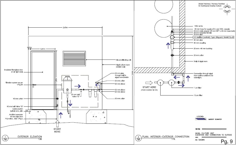
Refer to Technical Drawing – page 9. Sand filtered incoming seawater, diverted from the main supply line by a Y-junction (see technical drawing – 1/Pg4) and regulated by Valve Y, passes through a 40 mm pipe that connects to the filtration system. Valve Q (40 mm), located prior to the 25 µm coarse filter, allows a further control of seawater flow. The fine filtration system depicted here is typical of the system used throughout the complex and described in detail on the technical drawing diagram – 1/Pg5A. It consists of a coarse filter (25 µm) and two in-line cartridge filters of 10 µm and 1 µm; unions are fitted on either side of the cartridge housings, for ease of cleaning and replacement. Seawater supply line is reduced after the 25 µm coarse filter and prior to the finer cartridge filters. Filtered seawater (1 µm) is passed through a 20 mm pipe fitted through the container wall for supply to the algal culture vessels. Elbows in the line are fitted when necessary, and unions are added to facilitate cleaning.
Details of the connection of the incoming water through the container wall and to the interior of the containers are shown in the int-ext connection window on the same page (see technical drawing diagram – 2/Pg9). A 20 mm hole drilled through the container wall is fitted with a thru-hull fitting and made water tight with caulking adhesive. Immediately after entry into the container, a 20 mm union is fitted for ease of cleaning. The incoming seawater pipe is fitted with a 20 mm to 40 mm bushing, leading to a 40 mm coupling and pipe for connection to a Lifeguard vertical UV sterilizer. On the outflow side, the UV sterilizer is fitted with a 25 mm threaded female, connecting to a reducing 25 mm male adapter (25 mm NPT x 20 mm hose barb). In this way a 20 mm flexible hose may be adapted for supply of UV disinfected water to 4 l flasks and 100 l vessels. Details of the UV connection are illustrated in the technical drawing diagram – 3/Pg10. It is found that the UV sterilizer improves water quality for algal cultures by eliminating potential bacterial contamination; as efficiency of “sterilization” or disinfection is related to the speed of water flow, care is taken in providing a slow water flow through the UV sterilizer.
2.1.1.2 Floor plan
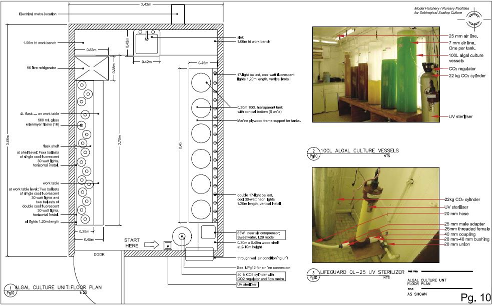
Refer to Technical Drawing – page 10. Climate control in the algal culture facility is maintained using an air condition unit affixed to one of the walls. This area must remain dry at all times to minimize proliferation of bacteria and molds. When required seawater and fresh water are supplied through flexible hoses adapted to their respective outlets. When not in use, both hoses are dismantled, leaving a clean and dry area.
The unit floor plan shows the position of the equipment necessary for serial inoculations from 500 ml cultures to large-scale algal cultures. In brief, 500 ml flasks are used as inoculum to 4 litres flasks, which in turn are used to start-up or boost 100 l cultures. Basic requirements are access to fresh water for cleaning of culture vessels, a sink for draining of fresh water or seawater, and UV sterilized seawater. Various
Technical drawing, Pg. 9
Algal culture unit: Elevation and connection to outside

Technical drawing, Pg. 10
Algal culture unit: Floor plan

methods are used for algal cultures; at the BBSR hatchery, it is found that aeration of cultures with an addition of CO2, for maintenance of constant pH, yields best results. For this reason, an airline is present providing a mixture of air and CO2 to every algal container.
At the entrance of the facility (on the right) is situated the UV sterilizer affixed on a 0.09 m2 shelf to the container wall. The flexible hose (20 mm ID) used for supplying incoming seawater should be long enough to provide seawater the entire facility. Above and to the right of the UV sterilizer is a second shelf, supporting an air compressor (Sweetwater, 65 W); it supplies air to the culture vessels in the facility. Below the air compressor, on the floor, is a 22 kg CO2 cylinder for the addition of carbon dioxide to the air supply. The connection of the CO2 tank to the airline is shown in detail in technical drawing – page 12. Six 100 litres tanks are located along the right wall of the facility. These transparent tanks with conical bottom are placed on a wooden frame, with access to the drainage valve below the frame (see technical diagram – 2/Pg10). Details of the drain are in the technical drawing diagram – 3/Pg12. A work-bench, useful for inoculating small cultures (500 ml and 4 l) is located at the far end of the container. In the middle of the counter is a sink allowing for drainage or overflow of seawater when not in use. Going counter clockwise, a small refrigerator is used for storage of chemicals needed for algal cultures. On the left hand wall, a counter top, with drawers beneath it for storage of small materials, supports 4 l flasks. Above it a 30 cm wide shelf is fixed to the wall for the holding of 500 ml flasks. Lighting is used 24 hours a day for rearing of algal cultures in Bermuda. A light bank is fixed to the wall behind the 100 l tanks, consisting of 17 vertical ballast of cool 30 Watt fluorescent light of 1.2 m length. For the 500 ml flasks, 4 ballasts of single cool fluorescent 1.2 m lights are installed horizontally. For the 4 l flasks, a total of 4 ballasts, 2 with double 1.2 m lights, and 2 with single 1.2 m lights are installed horizontally.
2.1.1.3 Ceiling plan
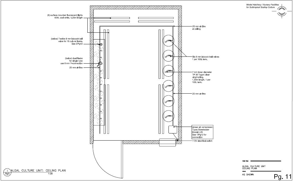
Refer to Technical Drawing – page 11. The ceiling plan outlines the contour of the 25 mm airline. Elbows are glued at the corners of the airline. The airline is secured to the ceiling by plastic clamps. In the airline, 8 mm holes are drilled and threaded with an 8 mm NPT tap drill bit and 8 mm NPT thread cutting tap. To these, an 8x8 mm NPT nipple is connected to an 8 mm labcock ball valve. This is similar to air connections described for the hatchery/nursery complex in Chapter 1 (see technical drawing diagram – 2/Pg7). There is one connection for every 100 l tank; for the 500 ml and 4 l flasks, one connection serves two flasks, joined together using a Y-connection (8–6 mm). Details of the air connection for the flasks are shown in the technical drawing – page 12. A total of eighteen air connections are available, allowing for twelve 500 ml flasks, twelve 4 l flasks, and six100 l tanks, respectively.
2.1.1.4 Details of air supply and 100 l culture vessels
Refer to Technical Drawing – page 12. All flasks and tanks should be supplied with a mixture of air and CO2. In the technical drawing diagram – 1/Pg12, mixing of CO2 with air is shown, and is further illustrated in technical diagram – 4/Pg12. Fittings for the Sweetwater air compressor are included with this model; the outlet is fitted with 15 mm flexible hose, secured with aluminium rings, and connecting to the 15 mm airline pipe with a 15 mm hose nipple and female fitting into a 15–25 mm bushing. From this bushing, air is directed through to a 25 mm elbow for supply throughout the container via a 25 mm airline. The CO2 cylinder, located nearby, is fitted with a regulator including a flowmeter, and controls CO2 input into the airline. From the flowmeter, a 7 mm ID Tygon tube connects to an 8 mm ID. tube leading to a hose barb x 8 mm male adapter fitting. The male adapter is threaded into the air supply via the 25 mm elbow depicted; in this way, CO2 is mixed with the air supply from the
Technical drawing, Pg. 11
Algal culture unit: Ceiling plan compres

sor. The technical drawing photo – 4/Pg12 shows the air/CO2 connection. The general rule is that the air supplied should consist of 0.5–5 percent CO2. It is found that one 22 kg bottle of CO2 lasts 5–7 days of continuous bubbling for all tanks.
Technical drawing diagrams – 2/Pg12 and 5/Pg12 show the air supply to individual culture vessels. Air mixture to each culture vessel is regulated by an 8 mm labcock ball valve (shown in the technical drawing photo – 4/Pg7). From the labcock valve, an 8 mm NPT x 7 mm barb male adapter connects to a 7 mm ID Tygon tube, directly supplying the algal culture. Bacteria filters are placed inline prior to entry into the flask, and help minimize air-borne bacterial contamination. The technical drawing photo – 5/Pg12 shows labels for these connections. There is sufficient pressure from a single valve to supply air to two flasks; the line can be divided if needed, by use of a Y-junction (8–6 mm). To ensure a tight connection, the smaller inner diameter tubing should be heated using a propane torch to fit the Y-junction.
Details of the 100 l vessels in technical drawing – 3/Pg12 describe the fitting of each tank for support, air supply and drainage. A wooden frame, made of marine plywood, is cut for the fitting of all tanks and is supported by concrete blocks on either end, for all tanks. Air is supplied to each tank using a similar connection to that described for the small vessels above, and Tygon tubing is connected to the bottom of the cone into an 8 mm barbed tube fitting. A drainage system is fitted to the bottom of the cones for harvesting of algae, and cleaning of tanks. A 50 mm male adapter is threaded into the base of the tank; an 8 mm hole is threaded into a 50 mm pipe for inflow of air and CO2 mixture. The 50 mm pipe is reduced to 20 mm and connects to a one-way 20 mm ball valve. A 30 cm diameter lid prevents detritus from falling into the vessel.
2.1.2 Chamber unit for master cultures
Master or stock cultures received from commercial phytoplankton suppliers arrive in 15 ml test tubes. For start-up of 15 ml test tube cultures and subsequent 125 ml Erlenmeyer flask cultures, an incubation chamber (Dual Program Illuminated Incubator 818 from Precision Scientific) is set at T= 25 °C and placed on a 12 hour illumination cycle. Next to the chamber, is an autoclave used for sterilizing small volumes of seawater, from 125 ml to 500 ml. The incubation chamber is maintained in a separate location from the large-scale culture unit. It allows for maintenance of clean stock cultures, independent of any contamination, which may occur in the larger cultures. Access to a workbench, and fresh water sink nearby allows for inoculation of cultures on a regular basis, and cleaning of culture flasks thereafter. Seawater supply differs for the stock cultures; low nutrient (and in this case “Sargasso”) seawater is used for master cultures, and treated as described below; whereas, 1 µm hatchery filtered seawater is used for 500 ml cultures and above.