SECTION 1 – THE MEDIA BED UNIT
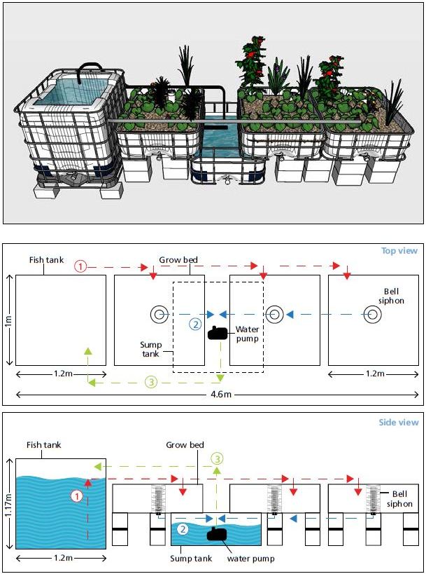
Water flow diagram
1. Water flows by gravitation from the fish tank to the media beds.
2. Water flows from the media bed into the sump tank.
3. Water flows back to the fish tank from the sump by using the water pump.
1. PREPARING THE FISH TANK
1.1 – Remove the two horizontal steel lengths attached to the top surface of the IBC tank holding the inner plastic container in place. The steel lengths are fixed with 4starheaded screws. Remove these four screws (Figure1) using a star headed screwdriver (Figure2) or star-headed key (Figure3). Once the steel lengths are removed, pull out the inner plastic tank
If there is no star key, cut the screws with an angle grinder.

1.2 – After pulling out the tank, draw a rough square shape on the top surface of the tank 5cm from the 4 sides of the tank (Figure4). Then, using the angle grinder (Figure5), cut along the square shape and remove the cut piece from the top (Figure6).
Once removed, wash the inside of the container thoroughly with soap and warm water and leave to dry for 24hours (Figure7).
The cut piece removed can be used as the fish tank cover.

2. INSTALLING THE FISH TANK EXIT PIPE
2.1 – On one side of the IBC tank, mark a point 12cm from the top and 12cm from the side of the tank (Figure8), and drill a hole at that point using the 57mm circular drill bit (Figure9). Insert a 50mm uniseal (Figure10) inside this hole.
Attention: the circular drill bit size should be 57mm and not 50mm (see Figure8).

2.2 – The fish tank exit pipe is made of 2lengths of PVC pipe (50mm) combined using a PVC elbow (50mm) and PVC coupler/straight connector (50mm) (Figure11). The length of PVC (50 mm) along the bottom surface of the tank is cut with horizontal slits 2–3mm wide by using the angle grinder (Figure12) to allow solid waste to enter the pipe but to prevent fish from doing so. The open end of the PVC length along the bottom surface of the fish tank is sealed with a PVC endcap/stopper (50 mm). Slot a short length of PVC (50 mm) through the uniseal (50 mm) and attach to a PVC elbow (50 mm) on the inside end (Figure 11) and then attach the other (vertical) pipe length to the elbow that is now connected to the uniseal (50 mm). Finally, drill a 2-3 cm diameter hole into the PVC elbow (50 mm) attached to the uniseal (50 mm) (Figure 13). This small hole prevents any air seal forming inside the pipe, which would drain all the water out of the fish tank in the event of power cut or if the pump stopped working. This is also called an accidental siphon. This step is not optional.

3. PREPARING THE MEDIA BEDS AND SUMP TANK
To make the 3 media beds and 1 sump tank, the 2 other IBC tanks are needed: the first to make the sump tank and 1 media bed, and the second to make the two remaining media beds. Take the 2 IBC tanks and remove the 4 steel profiles and pull out the plastic containers as shown before in Figures 1-3.
4. MAKING TWO MEDIA BEDS FROM ONE IBC
First, stand the plastic inner container upright (Figure 14) and mark, using a metre stick and pencil, two bisecting lines 30 cm from both sides of the tank (as seen in Figure 15). Make sure to mark the exact lines (shown in the Figure 15). Take the angle grinder and carefully cut along both bisecting lines marked out to create two uniform containers with a depth of 30 cm (Figure 16). Then, take both containers and wash them thoroughly using natural soap and warm water and leave them out to dry in the sun for 24 hours.

5. METAL SUPPORTS FOR BOTH MEDIA BEDS
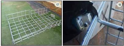
5.1 – Take the IBC metal support frame and cut out two support frames by following the same bisecting lines shown in Figure 14 using the angle grinder (Figure 17). When cutting the two 30 cm sides of the support frame, make sure to keep the two horizontal steel profiles intact as they will provide excellent support to the sides of the beds once they are full of water and medium (Figure18).
5.2 – Then, take both support frames and lay them out on the floor. Take the wood lengths (4lengths of 104cm, 1length of 42cm and 1length of 48cm) and place them on top of the support frame as shown in Figure19. These wood lengths keep the media bed horizontal, which is vital for the functioning of the bell siphons. Next, take the washed media beds and place them on top of the support frame and wood lengths (Figure20). Finally slot in the remaining wood lengths in between the plastic media bed and support frame on both sides of each bed to provide further support (Figure21).

6. MAKING A SUMP TANK AND ONE MEDIA BED FROM AN IBC
6.1 – Take the remaining IBC, place it upright and mark out, using a metre stick and pencil, only one 30cm bisecting line as seen in Figure22. Then, take the angle grinder and cut the inner plastic container and metal support frame at once by following the bisecting line (see Figure 22). Remove the 30 cm container (third media bed) from the remaining 70 cm container (sump tank) (Figure 23). Wash out both containers thoroughly with natural soap and warm water and leave in the sun for 24hours.

6.2 – For the third media bed, follow the same steps regarding the wood lengths as detailed above for the first two. Finally, take the sump tank container and drill two holes (25 mm diameter) using the conical drill bit as shown in (Figure 25) (25mm pipes will be inserted into both of these holes later, the pipes will drain water from each media bed).

7. PREPARING THE BELL SIPHONS
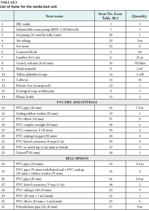
As explained in Chapter4 of this publication, bell siphons are simple mechanisms used to automatically flood and drain each media bed. The following materials are needed to make one siphon, so 3of each are needed in total:
35 cm media guard (110 mm PVC pipe)
27 cm bell [PVC pipe (75 mm) with flaired end + endcap/stopper (75 mm) + rubber washer (75 mm)]
16 cm standpipe (25 mm PVC pipe)
• Barrel connector (25 mm)
• PVC reducer (40-25 mm)
PVC female adaptor (25 mm x 1 inch)
PVC elbow (25 mm × 1 inch female)
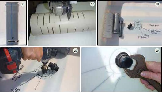
7.1 - First, create the bell. Take a 27 cm section of PVC (75 mm) and cut out 2 pieces as shown in Figure 26 using the angle grinder. Then, drill a hole (10 mm in diameter) using a drill bit about 1.5 cm from the two cut pieces as shown in Figure 26. Finally, seal one end of the bell using the PVC endcap/stopper (75 mm) and rubber washer (75 mm).
7.2 - Next, make the media guards from the 35 cm length of PVC pipe (110 mm) and cut 5 mm slots along their entire length using the angle grinder (Figure 27).
7.3 Now, take each media bed and mark their centre points in-between the two wooden lengths below as shown in Figure 28. Drill a hole (25 mm in diameter) at each centre point (Figure 29) and insert the barrel connector (25 mm) with the rubber washer placed inside the media bed. Tighten both sides of the barrel connector using a wrench (Figure 30).
7.4 – Screw the PVC adaptor (1inch – 25mm) onto the barrel connector (25mm) inside the media bed and then slot the standpipe into the PVC adaptor (1inch – 25mm). After, attach the second PVC adaptor (25–40mm) to the top of the standpipe (Figures31–33).
The purpose of this adapter is to allow a larger volume of water to initially flow down

the standpipe when the water has reached the top. This helps the siphon mechanism to begin draining the water out into the sump tank.
7.5 – Place the bell siphons and the media guards over the standpipes (Figures34–36).

7.6 – Finally, connect the PVC elbow (1inch–25mm) to the other end of the barrel connector underneath the media bed, which allows the water to flow out of the media bed (Figures37–39).

8. ASSEMBLING THE MEDIA BEDS AND SUMP TANK
8.1 – First, place the sump tank and brace it with six concrete blocks from each side (12blocks in total) as shown in Figures40 and 41. Make sure the blocks do not cover the holes already drilled into the sump tank (Figure42).

8.2 – Place the remaining blocks and the fish tank according to the distances described in Figure 43. The fish tank should be raised up about 15 cm from the ground. This can be done by using concrete blocks as shown in Figure 43. Place the three media beds (including the metal support frames and wood lengths) on top of the blocks (as shown in Figure44). Make sure the grow beds are secured on top of the blocks and horizontal by verifying with a spirit level. If not, slightly adjust the layout of the blocks underneath.

9. PLUMBING THE UNIT: FISH TANK TO THE MEDIA BEDS (DISTRIBUTION MANIFOLD)
9.1 - The plumbing parts needed for this section are as follows:
• Barrel connector, B-type (1 inch) x 3
• PVC tap (1 inch) x 3
• PVC endcap/stopper (50 mm) x 3 PVC elbow (50 mm) x 2
• PVC connector, T (50 mm) x 2
• PVC coupler (50 mm) x 3
150 cm of PVC pipe (50 mm) x 1
⚫ 85 cm of PVC pipe (50 mm) x 1
9.2 Go back to the "preparing the fish tank" (2.2) instructions. The last instruction shows a length of PVC (50 mm) slotted through the uniseal (50 mm) and exiting the fish tank. Take another PVC elbow (50 mm) and connect it to the pipe slotted through the uniseal (Figure 45). Then, using a PVC straight coupler (50 mm) and another PVC elbow (50 mm), connect the fish exit pipe to the distribution pipe (50 mm) at the same height as the top of the media bed (Figure 46).

9.3 - On each media bed, a valve is used to control the water flow entering the bed. To include a valve, first take a PVC endcap/stopper (50 mm) and drill a hole (25 mm diameter). Insert a barrel connector (25 mm) into the hole and tighten both ends using a wrench. Then, wrap Teflon tape around the threads of the male end of the barrel connector and screw the tap valve (1 inch) onto the barrel connector (Figures 47-50). There is one valve for each media bed for a total of three valves.

9.4 From the PVC elbow (50 mm) attached to the fish exit pipe, follow the pipe layout shown in Figure 51 that allows water to flow into each media bed. Materials include: PVC pipe (50 mm), PVC elbow (50 mm) and PVC T-connector (50 mm). Next, attach the pipe caps fitted with the valves to the PVC T connectors and PVC elbow connectors from the distribution pipe as in Figure 51, using one for each media bed. Use a PVC straight coupler (50 mm) if necessary.

10. PLUMBING THE UNIT: MEDIA BEDS TO THE SUMP TANK (DRAIN PIPE)
10.1 - Figures 52 and 53 show the media beds marked as A, B and C. For media bed A, attach a drain pipe of 60 cm length of PVC pipe (25 mm) to the elbow connection underneath the media bed (Figure 54), which exits from the bottom of the bell siphon standpipe. Next, slot the 60 cm length of pipe into the closest drilled hole on the side of the sump tank allowing the water to flow directly into the sump.
10.2 - Attaching media beds B and C (Figure 53): Under media bed C: attach a PVC elbow connector (25 mm to 1 inch) to the end of the barrel connector (Figure 54). Then, take a 2 metre length of polyethylene pipe (25 mm) and attach it to the drilled holes at the side of the sump tank (Figure 53 and 55).
10.3 - Do the same with media bed B using 1 metre of polyethylene pipe (25 mm) (Figure 55). Now, the water exiting media beds B and C will flow through separate polyethylene pipes (25 mm) into the sump tank.

Finally, it is advisable to fix the pipes underneath the beds to the metal frame using cable ties to relieve any pressure on the pipe fittings (Figure 54).

11. PLUMBING THE UNIT: SUMP TANK TO THE FISH TANK
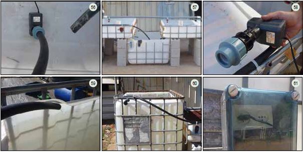
11.1 - Take the submersible pump and attach a polyethylene pipe (25 mm) using a PVC straight connector (1 inch - 25 mm), or any other connector that can attach the specific pump to the 25 mm pipe (Figure 56). Take a length of the polyethylene pipe (25 mm) that is long enough to reach the inside of the fish tank from the submersible pump (Figure 57). Attach one end to the submersible pump and the other into the top of the fish tank (see Figure 57-60). It is recommended to use the fewest connectors, especially elbows, between the pump and fish tank which will decrease pumping capacity.
11.2 Place the electric box in a safe place higher than the water level and shaded from direct sunlight. Make sure it is still waterproof after plugging in the water and air pump plugs (Figure 61).
12. ADDING THE MEDIUM AND RUNNING THE UNIT
12.1- All parts of the system are now in place except for the growing medium (volcanic gravel) in the beds. Yet before the media is added, it is recommended to fill the fish tank and sump tank with water and run the pump to check for any leaks in the system. While checking for leaks, remove the standpipe and bell siphon so the water flows straight into the sump tank. If leaks appear, fix them immediately where they arise by tightening the plumbing connections, re-applying Teflon to the treaded connections and making sure all taps are in their ideal position (Figures 62-67).
12.2 - Once all the leaks are fixed and the water is flowing smoothly through all components of the unit, re-assemble the siphon bell and standpipes fill the beds with medium to a depth of 30 cm (Figures 68-69)
