PREPARING THE FISH TANK (SAME AS IN MEDIA BED UNIT, SECTIONS1–2)
1. PREPARING THE FISH TANK (SAME AS IN MEDIA BED UNIT, SECTIONS1–2)
2. PREPARING THE MECHANICAL SEPARATOR AND BIOFILTER
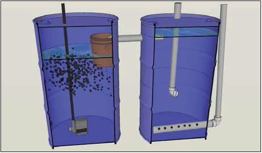
2.1 – Take two blue barrels (200litre) (Figure1) and cut out the shapes marked in the figures below (Figures2–4) using the angle grinder. Afterwards, wash both barrels with soap and warm water thoroughly and leave to dry in the sun for 24hours.

2.2 – The cut pieces of both barrels can also be used as barrel covers. They can be fixed to the top of the barrel using cable ties (see Figures5–6).

3. BARREL No.1 – MECHANICAL SEPARATOR
Inlet / outlet pipes of the mechanical separator
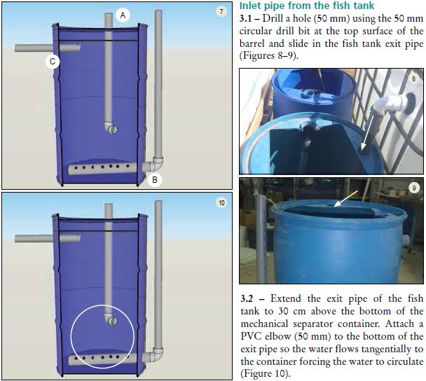
A. Inlet pipe from the fish tank.
B. Drainage pipe at the bottom of the mechanical separator.
C. Outlet pipe into the biofilter.
Inlet pipe from the fish tank
3.1 – Drill a hole (50mm) using the 50mm circular drill bit at the top surface of the barrel and slide in the fish tank exit pipe (Figures8–9).
3.2 – Extend the exit pipe of the fish tank to 30 cm above the bottom of the mechanical separator container. Attach a PVC elbow (50mm) to the bottom of the exit pipe so the water flows tangentially to the container forcing the water to circulate (Figure10).
Drainage pipe at the bottom of the mechanical separator
3.3 – Next, take a length of PVC pipe (50mm) and cut 2–3mm horizontal slits along the entire length using the angle grinder (Figure 11). Drill a hole (57 mm) on the outside of the barrel, 5cm above the bottom, and insert a uniseal (50mm) (Figure 12).
Slide the drain pipe (50mm PVC pipe cut with slits) through the uniseal and connect a PVC elbow (50mm) to the end of the pipe outside the barrel. Finally, attach another PVC pipe (50mm) that is 60–70cm in length to the elbow and make sure that the end of the pipe is above the maximum water level of the barrel (Figure13). The slits on the drainage pipe will allow solid waste to enter it and be flushed out by reclining the other vertical pipe attached outside of the barrel and pouring out the water from its end.

Transfer pipe connecting the mechanical separator to the biofilter
3.4 – Take a 65cm length of PVC pipe (50mm) and cut the same horizontal slits as above (3.3) for only the first 25cm of the pipe using the angle grinder (Figure14). Seal the slotted end of the pipe (50 mm) using a PVC endcap/stopper (50mm). Next, drill a hole (57mm) with the 57mm circular drill bit 70cm from the bottom of the barrel, and insert a uniseal inside the hole. Slot the transfer pipe (50mm) through the uniseal, making sure the end with 25 cm slits is completely inside the mechanical separator barrel (Figures15–16).

4. BARREL No.2 – BIOFILTER
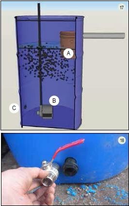
Inlet/outlet pipes of the biofilter
A. Inlet pipe from the mechanical separator
(Figure17).
B. Water outlet from the water pump.
C. Drainage tap.
25 mm drain tap
4.1 – Drill a hole (25mm) at the very bottom of the biofilter barrel and insert a barrel connector (V type, 25mm) into the hole and fasten it tight. Attach a tap (25mm) to the barrel connector on the outside of the barrel making sure the connecter is wrapped with Teflon to make a water tight seal (Figure18). The tap is used to flush out any solid waste accumulating at the bottom of the biofilter container.
Inlet pipe from the mechanical separator
4.2 – Drill a hole (57mm) using the 57mm circular drill bit 70 cm from the bottom of the barrel and insert a uniseal in the hole (Figure 19). Place the biofilter barrel adjacent to the mechanical separator barrel. Take the 65 cm PVC pipe length already attached to the mechanical separator barrel and slot it through the uniseal in the biofilter barrel as well. Now, both barrels are joined together using this transfer pipe (Figure20).

Preparing the solids capture bucket
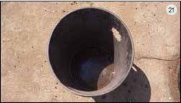
4.3 – Drill a 50 mm hole in the 20 litre bucket 5 cm below the top rim of the bucket (Figure21)
4.4 – Drill at least 20holes (8mm diameter) into the bottom of the bucket using an 8mm drill bit to allow water to drain into the biofilter (Figure21).
4.5 – Insert and slide the bucket along the 65cm transfer pipe inside the biofilter (the same 65cm pipe that connects both filter barrels (Figures22–23)
4.6 – Drill a 20mm hole into the transfer pipe and insert 6–10cm of PVC (20mm) (Figure23) to prevent the solids capture bucket from sliding off the transfer pipe.

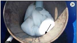
4.7 – Place filtration media (in this configuration we use volcanic gravel but perlon, sponge or other filters may be utilized) inside the bucket to capture any remaining solid or suspended waste (Figure24).
4.8 – Fill the biofilter with biofilter medium (Bioballs or bottle caps)
5. POSITIONING THE NFT PIPES
The materials needs for this section are as follows:
• 48 concrete blocks
• 1 m wood length (30 mm thick) x 1
• 1 m wood length (20 mm thick) x 1
• 1 m wood length (10 mm thick) x 1
5.1 – Place the concrete blocks according to the distances in Figure25. Each stand is made of 8blocks (two columns, each column 4blocks high. Place the wood lengths on

to the blocks: place the 3 cm thickness length along the column of blocks furthest away from the tank, the 2 cm thickness length on the middle columns and the 1 cm thickness length on the closest columns. This arrangement will create a small slope allowing the water to easily flow through the pipes and return to the biofilter barrel (Figure 25).
6. CONNECTING THE NFT PIPES AND COMMUNAL DRAIN
The materials needs for this section are as follows:
• 3 m of PVC pipe (110 mm) x 5
• PVC elbow (110 mm) x 2
• PVC T connector (110 mm) x 4 • PVC endcap/stopper (110 mm) x 5 Rubber washer (110 mm) x 15
• Natural soap
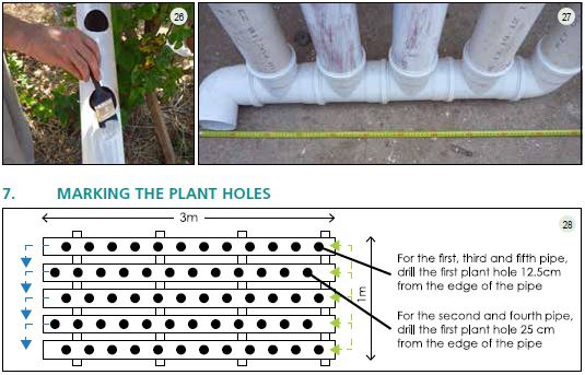
6.1 - Connect the pipe system according to Figure 27. Make sure that each pipe and
pipe fitting has a lubricated rubber seal fitted inside using the natural soap as a lubricant (Figure 26).
7. MARKING THE PLANT HOLES
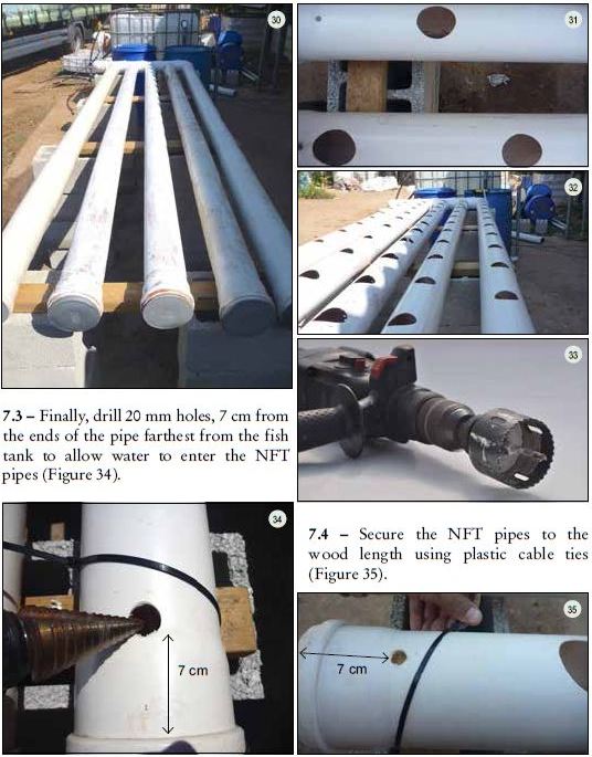
7.1 – Place the NFT pipes on top of the blocks and wood lengths and fit the five end caps (110 mm) to the ends of the pipe furthest from the fish tank (Figure 30). One effective method for marking the plant holes is to stretch and secure a thin piece of rope along the top of each pipe to mark uniform distances accurately.
7.2 – Mark a point every 25cm along the rope (Figure 29) which will be the centre point for the holes. Drill the holes (Figure33) according to the size of the net pots.

For optimal plant growing space, follow the triangular pattern shown in Figures 28 and 31.
8. CONNECTING THE END OF THE GROW PIPES BACK TO THE BIOFILTER
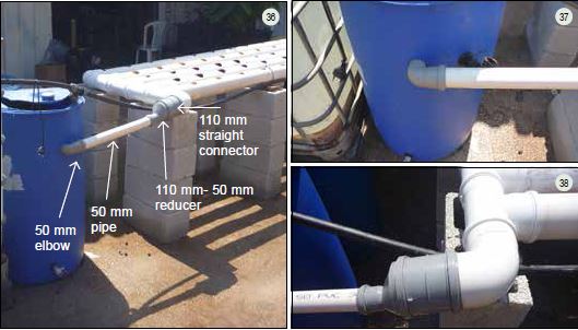
8.1 – Take a PVC straight coupler/connecter (110mm) and attach it to the final PVC elbow (110mm) of the common gutter of the NFT pipes (Figure27), which is made with a series of PVC T connections (110mm). Then, attach a PVC reducer (110–50mm) to the PVC straight coupler/connecter (110mm). This communal drain must connect to the biofilter. Drill a 50mm hole on the outside of the biofilter, 10cm lower than the bottom of the grow pipes. Fit a PVC elbow (50mm) into this hole. Use PVC pipe (50mm) to connect the elbow (50mm) to the reducer (110–50mm) allowing the water to flow from the NFT pipes back into the biofilter barrel. (Figures36–38).
9. INSTALLING THE DISTRIBUTION PIPING FOR EACH NFT PIPE
The materials needs for this section are as follows:
• PVC "push on" taps (20 mm) x 5
• PVC "push on" T connectors (20 mm) x 4
• PVC "push on" elbow connectors (20 mm) x 2
• Polyethylene pipe (20 mm)
• PVC adapter (20 mm - 3/4 inch x 1
• PVC elbow female connector (25 mm - 3⁄4 inch) × 1
Plumber's tape (Teflon)
9.1 - Connect all of the pipe and fittings according to Figures 39 and 40.

10. ADDING THE SUBMERSIBLE PUMP
10.1 – For this unit, the submersible pump is placed at the bottom of the biofilter barrel (Figures41a and 41b). Water is pumped from there to two locations: the NFT pipes and the fish tank. 80–90percent of the water flows to the fish tank while 10–20percent flows into the NFT pipes. The taps are used to control the water flow at each location.

11. PUMPING TO THE FISH TANK
11.1 – Connect the submersible pump to a length of polyethylene pipe (25mm) using a PVC adaptor, female (25mm – 1inch), or any connection that fits the pump. The polyethylene pipe (25mm) should be at least 1m long. Place a PVC T connection (25mm) at the end of the pipe to allow water to flow to the fish tank and the NFT pipes (Figures42–43).

11.2 – Attach a PVC pipe (25mm) to one end of the T connection (Figure42) long enough to reach the fish tank (Figure 44). Use a flexible pipe, if possible, to remove the need for additional connectors, which would reduce the pumping capacity of the pump. Attach a tap (25mm) to the end of the pipe to control the incoming water flow into the fish tank (Figure44).
11.3 – Next, take about 4metres of PVC pipe (25mm) and attach to the other end of the PVC T connector (25mm) coming from the water pump pipe inside the biofilter.
Attach this pipe (25mm) to the distribution manifold through the PVC elbow female connector (25mm – ¾inch) seen in Figure40, which will supply water to each NFT pipe (Figure44).

12. ELECTRIC BOX + AIR PUMP
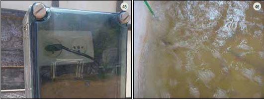
12.1 – Place the electric box in a safe place higher than the water level and shaded from direct sunlight (Figure45). Make sure it is still water proof after plugging in the water and air pump plugs, and put the air stones inside the fish tank (Figure46).
13. FINAL CHECKS
13.1 – All parts of the system are now in place. Before adding ammonia for cycling, fish or plants, fill the fish tank and both filters with water and run the pump to check for any leaks in the system. If leaks appear, fix them immediately (Figures47–49). The following steps show this process.

Mechanical separator drainage check (Figures50–52).

• Fill the biofilter with media and water (Figures 53a and 53b).
• Fill the mechanical separator with water (Figure 54).
• Mechanical separator and biofilter (Figure 55).

• Tighten the plumbing connections.
• Check all uniseals and taps for both filters.
• Re-apply Teflon to threaded connections.
• Make sure all valves are in their ideal position.
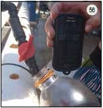
Finally, check the flow rate of the water flowing into each NFT pipe. The flow rate can be measured with a stopwatch and an empty 1litre plastic bottle. A flow rate of 1–2 litres/minute, which is the standard in NFT pipes, should fill the bottle in 1 minute (1 litre/minute) or 30 seconds (2litres/minute) (Figure56).
Once all the leaks are fixed and the water is flowing smoothly through all components, it is possible to start cycling the unit using ammonia (see Chapter5 of this publication for more details on this process).
14. PLANTING – MAKING THE PLANTING CUPS
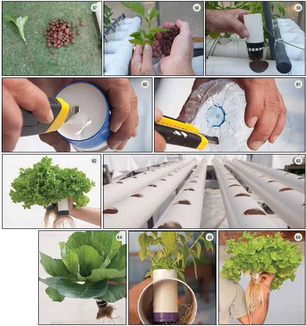
14.1 – For planting, follow what is shown in the following figures. Make sure the plant cup has enough holes to allow the root system to grow out into the pipe but also to prevent the growing medium from falling out. A plant cup made from a net cup and 10cm of PVC pipe (50mm) (Figures57–59).
A plant cup made from simple plastic/paper cups and a plastic bottle (Figures 60 and61). Plant roots clearly visible (Figures 62–66).
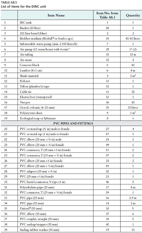
SECTION 3 – THE DEEP WATER CULTURE (DWC) UNIT
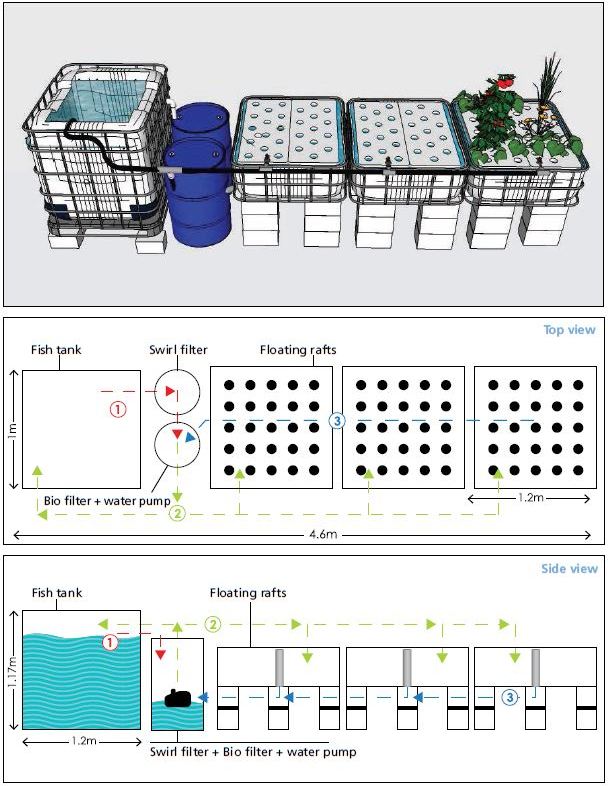
Water flow diagram
1. Water flows by gravitation from the fish tank to the swirl filter and biofilter.
2. Water is pumped, using the submersible pump, from the biofilter to the fish tank (80% of the flow) and
the DWC canals (20% of the flow).
3. Water flows back from the canals to the biofilter.
